Position Sensor Technology Comparison
for Hydraulic Cylinder Feedback
Edward E. Herceg
Chief Technology Officer
Alliance Sensors Group a div. of H.G. Schaevitz LLC
 Position
feedback sensors for hydraulic or pneumatic cylinders have used
one of three traditional technologies: Magnetostrictive,
Variable Resistance, and Variable Inductance sensors. While
other sensor technologies have occasionally been used
successfully in this application, the focus of this article is
the comparison among these three most popularly used
technologies. As the demand for increased control and
functionality has increased over the years, sensor- instrumented
cylinders are becoming more important in the heavy industry,
subsea, and mobile equipment worlds. Ultimately, a user or
systems integrator must determine the requirements of the
application and which technology best satisfies it on a total
installed cost versus performance basis. The strengths and
weaknesses of magnetostrictive, variable resistance, and
variable inductance sensors are discussed below, along with a
chart for feature-by-feature comparisons. Position
feedback sensors for hydraulic or pneumatic cylinders have used
one of three traditional technologies: Magnetostrictive,
Variable Resistance, and Variable Inductance sensors. While
other sensor technologies have occasionally been used
successfully in this application, the focus of this article is
the comparison among these three most popularly used
technologies. As the demand for increased control and
functionality has increased over the years, sensor- instrumented
cylinders are becoming more important in the heavy industry,
subsea, and mobile equipment worlds. Ultimately, a user or
systems integrator must determine the requirements of the
application and which technology best satisfies it on a total
installed cost versus performance basis. The strengths and
weaknesses of magnetostrictive, variable resistance, and
variable inductance sensors are discussed below, along with a
chart for feature-by-feature comparisons.
Initially, a point to be noted is that all of these common
sensing technologies utilize a long probe that extends into a
deep, small diameter blind hole which has been gun-drilled into
the internal end of the cylinder rod.
Magnetostrictive technology has been the preferred technology
for high accuracy applications. The sensor, often called an LDT
or MLDT, incorporates a stainless steel tubular probe and a
short toroidal permanent magnet assembly around it that is
installed in a counterbore in the piston. The most common
package is designed to thread the sensors' electronics housing
into an o-ring port in the back of a cylinder, with the long
slender probe inserted into the rod's bore. It uses the “time of
flight" principle to determine the magnet's position with high
accuracy and moderate response time. The magnet is used to
reflect a torsional mechanical pulse which is transmitted along
a special wire inside of the probe called a waveguide.
Typically, each of the magnetostrictive sensor manufacturers has
its own style of magnet with unique mounting features like the
number of holes, the hole pattern, etc. Magnetostrictive sensors
can consume a fair amount of power and are not the most
mechanically rugged sensors. They offer electrical performance
over mechanical robustness, because they are subject to shock
and vibration issues. Yet, while there are some potential
drawbacks mechanically, the magnetostrictive sensor's package
design is tailor-made for port-mounted in-cylinder use.
Variable Resistance potentiometer-type sensors, commonly called
pots, are selected where purchase cost is a driver and high
accuracy is not paramount. A resistance pot is usually embedded
into the cylinder's rear end plate, as opposed to the port
mounting of magnetostrictive sensors. It uses an insulated round
carrier which is attached to the internal end of the gun-drilled
cylinder rod and supports an electrically conductive wiper that
contacts the surface of a partially conductive plastic probe. As
the wiper moves along this plastic element, its resistance
changes in a linear fashion, making it fairly easy to determine
the carrier's position and, thus, the rod's position. Pots have
been seen as a good position measurement solution for use in
cylinders because of their ruggedness, favorable
stroke-to-length ratio, and their large analog DC voltage
output, which is a big percentage of the input voltage. The
major drawback to resistance pots is wearout, especially if the
cylinder is actuated at a high frequency, or even more
importantly, dithered over a short range to improve a system's
dynamic characteristics. Since a resistance pot is embedded into
the cylinder, replacement of a worn out pot can be very time
consuming and expensive, and could even result in the need for a
completely new cylinder.
Variable inductance position sensors have been used in the
cylinder industry but have not had the widespread recognition of
magnetostrictive sensors or resistance potentiometers. This
non-contacting technology has many significant advantages over
resistance potentiometers regarding product life and long-term
reliability, and usually can compete favorably with the
performance of magnetostrictive sensors in terms of linearity,
resolution, and frequency response, but at a significantly lower
cost. Equally important is the fact that variable inductance
sensors can withstand much greater shocks and vibration, such as
those commonly found in heavy industrial and mobile equipment
applications.
Linear variable inductance sensors cover the middle ground
between the higher level of performance and external port
mounting flexibility associated with a magnetostrictive sensor
and the ruggedness and price of an embedded resistance
potentiometer. These sensors operate by measuring the resonant
frequency of an oscillator circuit that uses an inductive probe
whose inductance is varied by the position of the gun-drilled
rod over it. Typically offered in full scale ranges of 4 inches
(100 mm) to 36 inches (900 mm), both port-mounted and embedded
packages are available, with connector and cable terminations
that match those found on most catalog magnetostrictive sensors.
These sensors offer either an analog DC voltage or current
output, with an SSI digital output available for OEM
applications. The variable inductance sensor presents a
non-contacting solution that does not require a ring magnet. In
fact, if a variable inductance sensor were installed to replace
an existing magnetostrictive sensor, the magnet can be left in
place in the cylinder rod end without interfering with the
sensor’s basic operation.

In the past few years, the requirements for instrumented
cylinders for subsea applications have dramatically increased.
Variable inductance sensors can be offered in a pressure-sealed
version that allows a user to install the sensor/cylinder in a
subsea environment in depths of 10,000 feet (3000 m) with 3000
psig of internal hydraulic pressure.
Remote field calibration is a standard feature offered on many
variable inductance sensors. This feature permits a user to
scale the output of the sensor while it is being installed on
the cylinder. With a simple push of a button to set the zero and
the full scale output points, the sensor will give the desired
full scale output over its newly set range, so it is no longer
necessary to scale the unit in an operating control system.
In another fluid power application, though not commonly used
inside of hydraulic cylinders, LVDTs are often used in spool
position feedback applications for two-stage hydraulic valves. A
short range variable inductance sensor with its simple inductive
probe inserted into a hole in the end of the main spool is very
often an easier installation than an LVDT that requires an
isolation tube to seal off the its core from the valve’s pilot
pressure.
Where there are still many fluid power applications where
resistance potentiometers and magnetostrictive sensors are a
good solution, these applications tend to fall to either side of
a bell curve. Recent electronic advancements and the flexibility
of package designs make variable inductance sensors very cost
effective for mainstream in-cylinder applications that tend to
be near the peak of that bell curve.
Alliance Sensors Group
102 Commerce Dr
Unit 8
Moorestown, NJ 08057
Ph # 856-727-0250
www.alliancesensors.com
|
IFPE & CONEXPO-CON/AGG 2014 attract
nearly 130,000, set new exhibit & education records
 The
future on display as global industry showcase spotlights new
product innovations, technology The
future on display as global industry showcase spotlights new
product innovations, technology
IFPE and CONEXPO-CON/AGG 2014 took center stage in Las Vegas
March 4-8 with tremendous energy and serious buyers. Total
registration of 129,364 soared past the last edition of the
shows as they achieved the second-highest attendance in their
history. The shows also set new records for exhibit space,
number of exhibitors and education tickets sold.
The co-located IFPE and CONEXPO-CON/AGG, at the Las Vegas (USA)
Convention Center, delivered a global showcase of the newest
product innovations and technologies for the construction,
construction materials and fluid power/power transmission/motion
control industries with more than 1,000 new products and
services on display.
Attendees also took advantage of the shows’ strong industry
education programs and the unparalleled opportunity to connect
with industry peers, take the pulse of what’s happening and
learn what the future holds.
“The enthusiasm and traffic on the show floor was just
incredible. Exhibitors cited the high quality of attendees; they
told us these were serious buyers and reported robust sales to
existing as well as new customers that exceeded their
expectations,” stated Megan Tanel, CONEXPO-CONAGG show director.
Quality Attendance, International Scope
IFPE & CONEXPO-CON/AGG 2014 maintained the growing international
scope of the shows with international registrations totaling
more than 31,000, or an increase of nine percent from the most
recent events. The number of countries represented increased to
170 from 159 in 2011, and the number of international attendees
matched the record 24 percent of total attendance set in 2011.
International attendance drew heavily from Latin America, China,
Canada, and Europe.
More than 75 percent of show visitors were in managerial roles
(with 36 percent of these with the top titles of president/owner
and vice president/general manager/chief financial officer).
Both shows set new records for exhibit space and number of
exhibitors, CONEXPO-CON/AGG with more than 2.35 million net
square feet of exhibit space and more than 2,000 exhibitors, and
IFPE with more than 161,000 net square feet and 400 exhibitors.
A record 41,000 education ticket sales were sold to the shows’
education programs, underscoring their relevance to helping
attendees succeed in today’s business environment.
“CONEXPO-CON/AGG and IFPE 2014 reflected the feeling of momentum
building in the industry. We are industry-run shows with
industry needs put first; these show numbers are a testament to
the value attendees, exhibitors, and other stakeholders derive
from their participation,” stated Melissa Magestro, IFPE show
director.
Global Industry Gathering Place
Among the show visitors were Acting U.S Deputy Secretary of
Commerce Patrick D. Gallagher, Acting U.S. Deputy Secretary of
Transportation Victor Mendez and former U.S. Rep. James
Oberstar, who served as chairman of the House Transportation and
Infrastructure Committee from 2007 to 2011.
The shows were chosen for the prestigious U.S. Department of
Commerce (DOC) International Buyer Program, which helps
facilitate global attendance. More than 50 official
international attendee delegations were organized by DOC as well
as show industry partners.
More than 95 allied associations and groups were official
supporting organizations, coming from the U.S., Canada and 16
other countries worldwide.
Several national industry associations held their annual
conventions or high-level board meetings at the shows; they
joined hundreds of other industry and company meetings, from
large events to smaller committees and other groups, all taking
advantage of the shows to meet and share knowledge and learn
from one another.
Education and Exhibits
The CONEXPO-CON/AGG 2014 education program covered 120 sessions
over 10 targeted tracks. The IFPE Technical Conference anchored
IFPE 2014 education, joined by half-day “college-level courses”
and a new Fluid Power Seminar series, from Hydraulics &
Pneumatics magazine.
CONEXPO-CON/AGG featured a new Demolition & Recycling exhibit
pavilion from the Construction & Demolition Recycling
Association (CDRA) and the Technology & Construction Solutions
pavilion from the Associated General Contractors of America.
IFPE featured exhibit pavilions from the Power Transmission
Distributors Association (PTDA) and for sensors manufacturers
and product suppliers.
Reinforcing the global scope of the shows were eight
international exhibit pavilions: CONEXPO-CON/AGG with China,
Ireland, Korea, Spain and United Kingdom, and IFPE with China,
Italy and Taiwan.
Show safety and education/training events at the shows included:
NRMCA International Truck Mixer Driver Championship, from the
National Ready Mixed Concrete Association
Lift Safety Zone, from NCCCO National Commission for the
Certification of Crane Operators and IPAF International Powered
Access Federation
Crane Operator Rodeo from Maximum Capacity Media
Industry recognition and networking events and programs also
amplified the show experience:
Innovation Awards program (from Diesel Progress magazine and
global powertrain specialist ZF Friedrichshafen)
Young Leaders event (from Construction Equipment magazine)
Quality of Life industry recognition campaign (from Dexter +
Chaney)
5K Run/Walk benefiting the non-profit Injured Marine Semper Fi
Fund (from Maximum Capacity Media)
Night at the Race Track hospitality event at the Las Vegas Motor
Speedway
Visit www.conexpoconagg.com and www.ifpe.com for the latest show
information.
To view Photos, visit online www.conexpoconagg.com or
www.ifpe.com in Media Services/Photos.
To hear what people onsite were saying about the show, visit
online at http://www.youtube.com/user/conexpoconagg -
and see these links:
http://www.youtube.com/watch?v=6YZAIRm4YEI&list=UUecbg2kv5U269fvLkNhvWGA
http://www.youtube.com/watch?v=Yx96r4FM5qE&list=UUecbg2kv5U269fvLkNhvWGA
http://www.youtube.com/watch?v=ZHbxEdmXXzU&list=UUecbg2kv5U269fvLkNhvWGA |
Solutions Come Together
 IFPE
is the leading international exposition and technical conference
dedicated to the integration of fluid power with other
technologies for power transmission and motion control
applications. Held every three years, the exposition showcases
the newest innovations and expertise. IFPE
is the leading international exposition and technical conference
dedicated to the integration of fluid power with other
technologies for power transmission and motion control
applications. Held every three years, the exposition showcases
the newest innovations and expertise.
IFPE 2014 Will Feature
-Over 400 exhibitors – making this the largest IFPE!
-Product concentration areas; making it easy for visitors to
locate specific products, services and exhibitors of interest
-More than 100 cutting-edge education sessions at the IFPE
Technical conference, focusing on the newest technologies, best
practices, the latest research and developments, including:
-Keynote presentations
-College-level courses in hydraulics and pneumatics
-Thousands of industry professionals from all sectors of the
fluid power, power transmission and motion control industries.
Aerospace/Defense
Agricultural Engineering
Amusement Machinery
Automotive Mfg./Supplier
Chemical & Petroleum Processing
Construction/Mining/Logging
Distribution
Electrical Machinery
Engineering Services
Factory Automation
Fluid Power Products
|
Instruments, Controls
Machine Tools
Material Handling
Metal Processing
Off-Highway Vehicles
On-Highway Vehicles (not autos)
Plastics/Rubber Working Machinery
Power Transmission |
Co-located with CONEXPO-CON/AGG 2014, the largest
international gathering place for the construction industries
|
 HAWE
Valves Assists Off-Road Motorsport Vehicles HAWE
Valves Assists Off-Road Motorsport Vehicles
CHARLOTTE, N.C.– January, 2014 – HAWE Hydraulics, a leading
global manufacturer and supplier of sophisticated hydraulic
components and controls for the mobile, industrial, and
renewable energy markets
Dakar 2014, is a legendary sporting event that challenges
drivers‘ endurance, racing skills and strategic navigational
competencies. This intense off-road race is made up of two
marathon stages that stretch across miles of South America’s
desertous terrain. Drivers take great precautions ensuring their
vehicles can withstand the wear and tear of the sand dunes and
off-road courses. For this reason HAWE Hydraulics took part in
servicing the dual hydraulically mounted jacks for the Chevy
Colorado Z71 Rally Raid prototype vehicles.
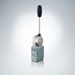 HAWE’s
reputation for long-lasting, durable products make them a
perfcect match for this project. SG 1L – AKS valves were used
for the racing vehicles. HAWE’s SG Directional Spool Valves
allow up to 400 bar, 100 lpm and serves to control the oil flow
and directional movements of the jacks. Since the valve system
is entirely made up of steel the housing unit is resistant to
pressure surges and leakages. This eliminates the chance of
hairline cracks or other damages caused by the harsh desert
conditions. HAWE’s
reputation for long-lasting, durable products make them a
perfcect match for this project. SG 1L – AKS valves were used
for the racing vehicles. HAWE’s SG Directional Spool Valves
allow up to 400 bar, 100 lpm and serves to control the oil flow
and directional movements of the jacks. Since the valve system
is entirely made up of steel the housing unit is resistant to
pressure surges and leakages. This eliminates the chance of
hairline cracks or other damages caused by the harsh desert
conditions.
About HAWE Hydraulics North America:
Sixteen years ago North America was introduced to HAWE Hydraulik
through its American subsidiary HAWE Hydraulics. Today, the
partnership brings more than 60 years of German engineering and
experience to North American mobile and industrial markets. HAWE
provides integrated services that include design, manufacture,
set-up, a distributor network, and local inventory. Based in
Charlotte, NC, HAWE Hydraulics is positioned to respond quickly
to service needs, as well as provide prototypes in a timely
manner. Headquartered in Munich Germany, HAWE Hydraulik is an
ISO 9001:2000 certified international supplier with a strong
focus on supporting rapidly developing niche markets.
|
 Altair
ProductDesign Unveils the World’s First Series Hydraulic Hybrid
Transit Bus Altair
ProductDesign Unveils the World’s First Series Hydraulic Hybrid
Transit Bus
BUSolutions LCO-140H to revitalize urban transit by increasing
fuel economy by 110 percent and reducing 12-year fleet
operations cost by $50 million for the average sized transit
authority
TROY, Mich. – Sept. 7, 2011 – Altair ProductDesign, a global
product development consultancy and wholly-owned subsidiary of
Altair Engineering, Inc., today unveiled the world’s first
series hydraulic hybrid transit bus. The LCO-140H (Low-Cost of
Ownership-1st 40-foot Hybrid) was developed under the
BUSolutions program in partnership with Automation Alley, in an
effort to revitalize public bus transportation in America.
Compared to the database of buses tested at Altoona, where the
Federal Transit Administration (FTA) certification program is
conducted, the LCO-140H fuel economy results are 110 percent
better than conventional diesel buses and 30 percent better than
the leading diesel-electric hybrid buses available today. The
LCO-140 achieved an industry high fuel economy of 6.9 mpg when
tested using the downtown “stop-and-go” duty cycles and test
protocol established by the FTA for transit bus certification
testing.
BUSolutions is projected to lower the cost of ownership by
$170,000 per bus as compared to a conventional diesel bus. With
the average local transit authority operating approximately 300
buses, the savings could reduce a city’s cost of transit bus
operation by approximately $50 million. When compared to an
estimated $27 million increase in operational costs for a
similar electric hybrid fleet, it is clear the LCO-140H could
revolutionize the transit industry by providing reduced fuel
consumption and emissions while improving the fiscal performance
of a regional transit authority.
BUSolutions has been a collaborative effort between public and
private entities to research, develop and commercialize advanced
transit bus systems that are significantly more fuel efficient,
have lower operating and maintenance costs, are competitively
priced and can operate without updating the infrastructure of
existing transit authorities.
In addition to investments by Altair and Automation Alley,
BUSolutions has been funded by multiple federal and state
programs including the FTA and the Michigan Economic Development
Corporation (MEDC). It also has received exceptional local
support by southeast Michigan congressional members,
transportation industry partners, and local transit authorities
SMART and the Detroit Department of Transportation (DDOT).
“This project has been a collaborative effort from start to
finish throughout the development, design and test phases. We
would not have exceeded the goals we had set for ourselves had
we not applied our knowledge and unique technologies to produce
this revolutionary bus,” said Mike Heskitt, chief operating
officer at Altair ProductDesign. “BUSolutions demonstrates
Altair’s
expertise and capabilities as a concept-to-release, full vehicle
development partner.”
“We are thrilled to have partnered in the BUSolutions program
that is putting Michigan at the forefront of solving emerging
public transit technology issues through innovation and
collaboration,” said Ken Rogers, executive director at
Automation Alley. “Goals were set when this program started to
produce a transit bus that was more fuel efficient, more
affordable and more cost effective to operate for city transit
authorities, and this project has both met and exceeded those
goals.”
Additionally, BUSolutions strategically partnered with regional
and global high-tech manufacturers that assisted in
incorporating state-of-the-art components and technologies from
the transportation sector. Program sponsors include Parker and
Meritor, which contributed significant driveline systems and
knowledge. Various levels of support have been provided by PRAN,
Sika Corporation, Meritor Wabco, Alcoa Wheel Products, Carrier
Corporation, LADD Industries,Haldex, Shaw Development, Tenneco,
USSC Group, Cummins Bridgeway, Multicolor Specialties and
Williams Controls.
Altair has worked closely with local transit authorities, SMART
and DDOT, to ensure the newly designed bus platform will meet
regulatory requirements and address the needs of bus drivers and
riders. Altair also established the BUSolutions Advisory Board
to offer insight into broader community needs, as well as
perspective on actual ridership issues and public-interface
ergonomics. As a result, Altair ProductDesign successfully
engineered the bus to incorporate design principles that will
enhance the rider experience.
The LCO-140H Bus will also be demonstrated at the American
Public Transportation Association (APTA) Expo in New Orleans
Oct. 3-5 at booth #2281. For more information, visit the Altair
events website.
About BUSolutions
Launched in 2005, the Altair BUSolutions program was established
to develop and commercialize an advanced bus platform that
lowers the total cost of ownership and environmental impact of
commercial buses without updating the infrastructure of existing
transit authorities. Leveraging the company’s deep domain
knowledge in vehicle systems and cutting-edge, simulation-driven
design practices to develop the design, Altair successfully
partnered with Automation Alley, Michigan’s largest technology
business association, to secure federal funding to build working
technology demonstrators for future commercialization. For more
information, visit www.altairbusolutions.com.
About Altair ProductDesign
Altair ProductDesign is a global, multi-disciplinary product
development consultancy of more than 500 designers, engineers,
scientists, and creative thinkers. As a wholly owned subsidiary
of Altair Engineering, Inc. (www.altair.com), this organization
is best known for its leadership in combining its engineering
expertise with computer aided engineering (CAE) technology to
deliver innovation and automate processes. Altair ProductDesign
firmly advocates a user-centered, team-based design approach,
and utilizes proprietary simulation and optimization
technologies (i.e., Altair HyperWorks) to help clients bring
innovative, profitable products to market faster. To learn more,
please visit www.altairproductdesign.com.
|
|
 |
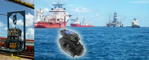
Twin Cities Manufacturer
Part of the Solution to Stop Gulf Oil Leak
Modified valve from Continental Hydraulics Helps Waterjet System
Unclog Containment Dome
(Minneapolis, Minn.) – There’s no question the BP oil leak
crisis takes engineering, thought and industry best practices.
Intervention is rough according to James Miletich of
Oceaneering’s ROV Division. “You’re always fighting something.
It’s never easy,” he said.
Recently, hydrate ice crystals formed inside BP’s 40-foot-tall
containment system aimed to capture leaking oil—and ultimately
clogged the system. Hydrate gases crystallize like ice in cold
waters and high pressure deep beneath the ocean’s surface.
Minnesota company Continental Hydraulics, in partnership with
Jet Edge, Inc. and Chukar Waterjet, Inc. developed a solution to
help fight the problem. The company’s DO8 valve was used to
operate Jet Edge’s waterjet pump enabling the jet stream to
blast away the hydrate crystals.
“The timeliness and schedule was intense—but we were pleased to
deliver a modification to our product capable of withstanding
the harsh undersea environment and enormous water pressure at a
depth in excess of 5,000 feet,” said Continental Hydraulics
general manager Jeff Brandt.
Jet Edge’s custom engineered waterjet intensifier pump was
dropped into the sea to power a robot-operated waterjetting
lance— eliminating the hydrates. This equipment is the
first-known waterjet system capable of operating in water depths
in excess of 5,000 feet, opening a new frontier for waterjet
technology.
Chukar Waterjet, Inc. general manager Bruce Kivisto said, “We
worried about 2300 pounds of force and the harsh exposure to
that valve. Continental Hydraulics recognized the importance,
the challenge and delivered a critical component to our
success.”
Kivisto provided onsite application and engineering services
throughout the project, recently returning from several weeks
aboard a boat just 50 yards away from the Discoverer Enterprise.
He says the solution appears to be working and will continually
be monitored.
###
Continental Hydraulics of Savage, Minn. is a manufacturer of
high performance hydraulic pumps, valves and power units. Their
products are used in some of the most severe conditions and
their reputation for superior durability and performance
continues to grow. The engineering staff at Continental is
continually at work to improve current products and develop new
fluid power technologies. In addition, Continental Hydraulics
specializes in response time and delivery for challenging custom
orders. For more information, visit
www.continentalhydraulics.com.
|
|
|
Do Minor Oil Leaks Really Matter?
By Jack Weeks
 We
are often asked if minor leaks are really much of a concern.
Repairing them takes valuable time that most maintenance shops
feel should be devoted to issues that could halt production.
Everyone knows that a ruptured hose needs to be addressed right
away. But the mistaken belief that a minor leak doesn't cause a
problem is certainly not uncommon. It is even a little
surprising how many people seem to believe that hydraulic
machines are "supposed to leak a little". We have heard
everything from "The oil that bypasses the cylinder seals helps
to keep the rods lubricated" to "The leaks in our system help
keep our oil fresh since we have to replace so much of it all
the time". These same people however would be dissatisfied if
their automobile's power steering pump, automatic transmission
or brake lines "leaked a little bit". We
are often asked if minor leaks are really much of a concern.
Repairing them takes valuable time that most maintenance shops
feel should be devoted to issues that could halt production.
Everyone knows that a ruptured hose needs to be addressed right
away. But the mistaken belief that a minor leak doesn't cause a
problem is certainly not uncommon. It is even a little
surprising how many people seem to believe that hydraulic
machines are "supposed to leak a little". We have heard
everything from "The oil that bypasses the cylinder seals helps
to keep the rods lubricated" to "The leaks in our system help
keep our oil fresh since we have to replace so much of it all
the time". These same people however would be dissatisfied if
their automobile's power steering pump, automatic transmission
or brake lines "leaked a little bit".
So how much does a minor leak cost? To answer that question, we
have to first explore all of the costs involved. Most people
think that the only cost is the amount of oil that has to be
unnecessarily replaced. But this is not the only cost associated
with hydraulic leaks. The actual costs include:
Replacement Oil
Safety
Environmental Concerns
Cleanup Costs
Disposal
Contamination
Loss of Machine Efficiency
Replacement Oil
This is the most obvious cost. A drop of hydraulic oil doesn't
cost very much even at today's prices. But if your machine loses
a drop of oil every second, it adds up. A drop every second will
equal about one gallon per day. 30 gallons per month and 365
gallons per year. Depending on your geographic area, the type of
oil you use in your machine and the volume you purchase you pay
between $6 and $10 per gallon. This means that a leak that loses
one drop per second (most machines lose many times that) is
costing you between $2190.00 and $3650.00 each year in
replacement oil alone.
Safety
The cost of replacement oil is bad enough but oil leaks pose a
safety hazard in almost every facility we have visited. The cost
of safety hazards is hard to calculate. But even one incident
can cost a few hundred dollars or a few million.
Environmental Concerns
Not everyone agrees with the Environmental Protection Agency's
standards and policies. But we doubt anyone believes that EPA
requirements will become more lenient in the near future. If any
changes are made in EPA standards, they are likely to include
stricter controls and heavier fines and penalties. Currently an
uncontained spill of more than one gallon can require EPA
notification. Fines in the millions of dollars are not uncommon.
Cleanup Costs
Often the costs of routine cleanup are ignored, but that doesn't
make them go away. Time devoted to cleaning up from a leak is
time that could be spent on more productive endeavors and could
result in overtime costs that would otherwise not have to be
incurred. And we cannot ignore the cost of cleanup equipment,
absorbent pads and detergents. Annual cleanup costs can easily
add $2000 or more to our drop-per-second leak.
Disposal
Those of us who can remember a time when waste oil companies
paid for the privilege of coming to empty our waste hydraulic
oil tanks can probably also remember getting change back from a
five dollar bill after having someone else fill up our gas
tanks, check our oil, check our tire pressure and clean our
windshield. These days an environmentally acceptable means of
disposing of waste oil can cost $3 per gallon or more. There's
another $1100 annual cost to our minor leak.
Contamination
It's easy to forget that if oil has a way out of the machine,
contaminants have a way in. Airborne contaminants, particles and
water all can wreak havoc with a hydraulic machine. Over 96% of
all hydraulic failures can be directly traced to contaminants in
the oil. Not all of those contaminants come from an oil leak of
course, but any that we can stop will pay big dividends in parts
that do not have to be changed unnecessarily, reduced down time
and greater intervals between flushing or changing the oil.
Loss of Machine Efficiency
A machine that leaks is working harder than it has to. This
means that, while the machine appears to be functioning as it
should, our energy costs have increased. Suppose our
one-drop-per-second leak causes the power bill to increase by
five cents per day. That's another $18.25 in annual cost. Not a
huge amount, but it could probably buy us dinner somewhere. And
it adds up if it occurs in several machines.
So assuming that no one gets hurt from slipping on oil and the
EPA doesn't have to visit, each drop-per-second leak is costing
somewhere between $5000 and $7000 every year. And hydraulic
leaks, unlike paper cuts, do not heal. They gradually get worse.
At some point, what starts as a "minor" leak can become a
machine outage. No leak is so minor that it should be ignored.
GPM Hydraulic Consulting, Inc.
Box 1376
Monroe, GA 30655
(770) 267-3787
www.gpmhydraulic.com |
|
|
- Funny Noises
By Jack Weeks
 Not
long ago on a consulting job, I noticed a loud hissing sound
coming from a machine (not the machine I had been called to
help diagnose). I asked the man I was working with about it
and he said, "It's done that as long as I've been here. I
guess it's supposed to sound like that - the machine works
fine.". But it didn't sound normal to me. Looking a little
more closely, I noticed a very large, relatively new heat
exchanger installed on the machine. The man I was with
explained that the machine used to overheat, so they
installed a larger heat exchanger and that fixed the
problem. Watching and listening through a full cycle of the
machine, I noticed that the hissing sound was much louder at
idle than while the machine was running. Placing my hand on
the relief valve, I found that it was so hot I could not
keep my hand on it. The problem was obvious - at some point,
someone turned up the pressure on the pump compensator and
it was now adjusted above the system reliefvalve setting.
The pump was operating at full stroke all of the time. Any
flow not being used by the machine would dump across the
relief valve. I suggested that he reduce the setting on the
pump. I could tell that he didn't really want to, because he
was afraid the machine would stall. So I told him to wait
until the machine was idle again, then turn it down just a
quarter turn. Once the machine was in an idle condition, he
made the quarter turn counterclockwise on the compensator
and, with a puzzled look on his face, noticed that the
pressure reading on the gauge did not change. He made
another Not
long ago on a consulting job, I noticed a loud hissing sound
coming from a machine (not the machine I had been called to
help diagnose). I asked the man I was working with about it
and he said, "It's done that as long as I've been here. I
guess it's supposed to sound like that - the machine works
fine.". But it didn't sound normal to me. Looking a little
more closely, I noticed a very large, relatively new heat
exchanger installed on the machine. The man I was with
explained that the machine used to overheat, so they
installed a larger heat exchanger and that fixed the
problem. Watching and listening through a full cycle of the
machine, I noticed that the hissing sound was much louder at
idle than while the machine was running. Placing my hand on
the relief valve, I found that it was so hot I could not
keep my hand on it. The problem was obvious - at some point,
someone turned up the pressure on the pump compensator and
it was now adjusted above the system reliefvalve setting.
The pump was operating at full stroke all of the time. Any
flow not being used by the machine would dump across the
relief valve. I suggested that he reduce the setting on the
pump. I could tell that he didn't really want to, because he
was afraid the machine would stall. So I told him to wait
until the machine was idle again, then turn it down just a
quarter turn. Once the machine was in an idle condition, he
made the quarter turn counterclockwise on the compensator
and, with a puzzled look on his face, noticed that the
pressure reading on the gauge did not change. He made
another
quarter turn. Still no change. Then another and another. "I
don't think this valve is working - turning it has no effect
on the pressure.". But I could still hear the relief valve
dumping so I explained to him that the system pressure was
currently being determined by the relief valve, not the pump
compensator. After approximately one and one-half full turns
of the compensator adjustment, the hissing sound stopped.
The gauge pressure began to drop. I had him stop when the
pressure on the gauge was about 250 PSI below where it had
started. The machine was noticeably more quiet. "When it
starts back, I don't think it will work without stalling now
that we have the pressure this low.". I said,
"Let's see.". When the machine began to cycle again, not
only was it quieter than it had been, but the actuators were
moving faster than they had before. I also told him that the
current draw from the electric drive motor would likely be
considerably less than before, too. The original heat
problem had never really been addressed, only one of the
symptoms had been masked.
This is by no means an isolated incident. Hydraulic machines
simply do not make unusual sounds unless something is wrong.
Just because the machine still appears to be functioning
normally does not mean that it needs no attention. And a
strange sound coming from the machine is often one of the
very first signs of impending trouble. It has always been
amusing to me how the same person who would take his car
immediately to a mechanic if he heard a strange sound will
ignore unusual noises in a multimillion-dollar hydraulic
machine. Of course, there is no such thing as a silent
machine. All industrial machines make noise. But sound is a
form of energy and any unusual sound is, at the very least,
a waste of some of the energy applied to the machine. There
are hundreds of abnormal sounds a machine may make and an
exhaustive list of every possible one could probably
fill a book. All of them can mean trouble, but in a
hydraulic machine, a few of them are harbingers of serious
issues that can cost a lot of money in very little time.
Relief Valves and Other Pressure Controls
Relief valves, for the most part, are designed to open only
when something is wrong. Typically they are installed to
keep system pressure from reaching dangerous levels With
only a few exceptions, hydraulic machines are not designed
to dump across their relief valves continuously. The hissing
sound described above and a significant temperature gain
across the relief valve are the most obvious indications
that a relief valve is dumping. Heat is also a form of
energy, so when a relief valve dumps a corresponding
increase in current draw will usually be indicated on the
electric drive motor. The excessive heat will not only waste
energy but will also degrade the hydraulic oil. Most relief
valves are set well above normal operating pressure, so when
they are dumping the system pressure is usually higher than
normal. This causes excessive wear all over the machine. If
left
unchecked, shock spikes attack hoses, fittings, pipe clamps
and seals. Mechanical wear to bushings, bearings, supports
and connectors is also accelerated. Other pressure controls,
such as reducing valves and counterbalance valves are often
intended to be open regularly. But this doesn't mean they
should always make excessive noise. A whistling sound or
erratic hissing often suggests that they are improperly
adjusted or stuck open. A good rule of thumb is if it
doesn't sound right, it probably isn't. Slamming of
actuators, stalls and excessive heat generation are the
early symptoms of problems with these valves.
Pump Cavitation
A pump that is cavitating makes a steady, high-pitched
whining sound. Since the sound is steady and does not
reflect changes in the movement of the machine, it is often
confused with bearing wear in the pump. Often a pump is
replaced unnecessarily because it is cavitating. Cavitation
is caused when the pump is trying to deliver more oil than
it can draw into its suction line. This may be because the
oil is too cold and the viscosity is high or because the
drive motor has been mismatched and is turning the pump too
fast, but most of the time cavitation is caused by some
blockage in the pump suction. Usually this is the result of
a plugged suction strainer or filter. Naturally, when a pump
is
replaced, its suction filter element is changed or its
suction strainer is cleaned while everything is apart. The
cavitation stops when the new pump is installed, but
actually it was the cleaning of the strainer or the
replacement of the suction filter element that stopped the
cavitation.
In addition to the steady high pitched whining sound,
another symptom of cavitation is a reduced flow from the
pump, which will result in a reduced speed of the machine.
Obviously, a pump can deliver no more oil than it can get
into its suction line. The pump will destroy itself if the
cavitation is not addressed.
Pump Aeration
Often confused with cavitation because of its similar sound,
aeration occurs when outside air enters the suction side of
the pump. The pressure in the pump suction line is below
that of the surrounding atmospheric pressure, so a leak will
result in air coming in, not hydraulic fluid coming out. It
can be distinguished from cavitation by its somewhat more
erratic whining sound. The sound of cavitation is from the
implosion of air molecules suspended in the oil. Since the
molecules are distributed very evenly throughout the oil,
the sound of cavitation is very steady. But the amount of
air that leaks into the suction side of a pump is heavily
dependent upon the flow of hydraulic oil. The sound will
therefore change as changes occur in the machine. It will
also likely be accompanied by a sound similar to gravel or
marbles rattling around inside the pump. If you can view the
oil in the reservoir (most reservoirs have screens and
baffles that get in the way of seeing the oil) you may also
note some foaming of the oil. If a pump is allowed to aerate
it will wear rapidly. But beyond damage to the pump, the
rest of the hydraulic components will also be at risk.
Aerated oil causes a number of
problems. When air is in the line, the machine will perform
sluggishly (think about the last time you had air in the
brake lines of your car). Air viscosity is well below that
of oil. The reduction in viscosity will result in leaks,
faiure to lubricate and heat problems. Air also becomes
somewhat unstable at the high pressures hydraulic machines
are operated, so corrosion and seal damage are likely. Air
that enters the suction line probably also brings with it a
host of contaminants to damage components.
If a leak in the suction line is suspected, squirt oil along
the line. If aeration ceases briefly, you have found your
leak. A worn shaft seal on a fixed displacement pump can
cause it to aerate. Spray some shaving cream around the
shaft seal and see if holes are drawn into the foam.
Sometimes there is no float switch to shut the machine down
when the oil level is too low. If the level of the oil gets
too close to the suction strainer, a vortex will develop
drawing air into the suction line along with the oil.
Aeration can also be caused by the wrong shaft rotation or
by improperly aligned couplings.
Directional Valve Noise
For the most part, directional valves should operate quietly
- no more than a faint "click" on very quiet machines. The
small amount of noise a directional valve makes is almost
always completely drowned out by the rest of the machine. If
you can hear a directional valve spool shift, chances are
very good that there is a problem. If the pilot chokes are
improperly adjusted on a two-stage directional valve, it
will audibly slam when it shifts. The spool can easily be
damaged, but the greater issue is the shock it introduces to
the machine. Sudden movement of the valve spool causes shock
throughout the machine and the weaker points of the system
will suffer. Adjust the pilot chokes for smooth shifting of
the spool and greater component longevity.
Cylinder Noise
Cylinders should move with almost no noise. If a cylinder
makes noise, it may be binding or slipping. A bent rod will
wear seals and mechanical linkages rapidly. Slippage
degrades the performance of the machine and sends
contaminants from the resulting worn seals out to other
components. A noisy cylinder should be rebuilt or replaced
as soon as possible.
Hydraulic Motor Noise
Hydraulic motors can make many of the same noises as
hydraulic pumps. Just as pumps can aerate and cavitate, so
can motors. And the same results will develop. A motor that
is cavitating will destroy itself rapidly. This usually
occurs on motor drives that have loads that can be overcome
by gravity, causing the load to "run away". A meter out flow
control or brake valve can correct this.
Listening to a machine and paying attention to the sounds it
makes can pay off in large dividends by catching problems
early before they become outages.
Jack Weeks entered GPM’s organization in January of 1997 as
a CAD draftsman and hydraulic instructor. He has trained
thousands of electricians and mechanics in Hydraulic
Troubleshooting methods. His computerized animations have
made GPM's presentations and training CD's the recognized
leader in the industry. He received his education from the
Georgia Institute of Technology School of Electrical
Engineering and the Department of State Foreign Service
Institute. Jack is an experienced draftsman and taught
telecommunications equipment operation and repair for the
Central Intelligence Agency at American embassies overseas.
GPM Hydraulic Consulting, Inc.
Box 1376
Monroe, GA 30655
(770) 267-3787
www.gpmhydraulic.com |
|
|
 The
"Hole" Story Behind Cartridge Valve Performance The
"Hole" Story Behind Cartridge Valve Performance
Latest precision bore machining technology drives performance
and quality improvements
by
Rich Moellenberg
Manager, Global Technology Support
Sunnen Products Company
A new generation of honing technology is playing a vital role
today in improving product performance for fluid power
components, providing manufacturers a unique ability to
size and finish valve bores precisely, with exceptionally high
process capability (Cpk) levels. The new honing technology,
known as precision bore machining, can control bore size
with quarter-micron accuracy (0.00001 inch), correct geometric
errors in the bore, and produce a specific surface finish with
lubrication and seal enhancing properties.
What's this mean in terms of performance in a cartridge valve?
Conventional honing
straightens a valve bore and precisely sizes it. This allows
reduced clearance between the
bore and mating parts, greatly reducing valve leakage. The
tighter fit and correct geometry
help lower hysteresis and allow higher operating pressures with
overall greater system
efficiency. Finally, honing creates surface finishes that wear
at a slower rate to enhance
valve life. The crosshatch finish left by conventional honing
improves the uniformity of
the lubricating film between sliding parts for more consistent
performance, especially in
adverse operating conditions.
What is honing? Conventional honing is an abrasive machining
process whereby a tool
with expanding stone assemblies rotates in the cylinder bore,
while the tool or the part
reciprocates rapidly during the process. A conventional honing
tool may contact the entire
length of the part's bore, giving this process a unique
capability to correct geometric
error in the bore shape. Honing generates little heat and
stress, so the surface integrity
of the bore is excellent and can be finished to a specified
level of roughness.
It may seem a contradiction, but attaining performance
enhancements with honing
actually lowers costs for the valve maker and can create
opportunities to offer longer
product warranties. Here's how.
Any valve manufacturer can purchase basic screw machined
components from high-
quality vendors, but tolerances for these parts are rarely
"state of the art" precise. A
bore tolerance of 0.002 inch (0.05 mm) is considered acceptable
by most machinists, while
honing produces bore tolerances of less than 0.00005 inch
(<0.0013 mm).
In terms of the valve manufacturing process, various hole making
operations, such as
boring, drilling and reaming are capable of producing excellent
tolerances, but when a
manufacturer requires a high process capability – such as 1.33
Cpk – for quality purposes,
the acceptable tolerance level must shrink to meet this. For
rule-of-thumb purposes, when
the target is 1.33 Cpk process capability, manufacturers find
they have to hold about 75% of
the print tolerance; at 1.67 Cpk, it drops to about 60% of
tolerance, and the average of the
measurements needs to be targeted very tightly on the mean of
the tolerance. Holes produced
satisfactorily on a lathe for years that suddenly have to meet
process capability of 1.33 or
1.67 Cpk may require a much narrower bell curve of distribution
to stay between the upper
and lower support limits. "Flyers" at the fringes of the curve
become unacceptable.
How does "process capability" translate to real world results?
The classic Motorola
Six Sigma quality program (six sigma is a 2.0 Cpk process
capability) projected a defect
rate of 3.4 per million.
High process capability requires a machining operation that's
easy to "dial in" with
great precision, and very stable once the process is
established. For example, a lathe may
get to just a certain value, but if tweaked a little, will jump
to a value out of spec and
throws the process off. A computer-controlled hone can easily
get within 10 millionths of a
specified size, and with the resolution on the feed systems of
today's machines, the
variability is very small. Size control is not the only issue.
Honing allows tailoring of
the surface finish and then leaves a crosshatch pattern on the
bore of the cage.
Alternative processes, such as turning and single-pass honing,
cannot produce
conventional honing's characteristic crosshatch pattern on the
bore surface. Conventional
honing leaves a very desirable crosshatch pattern, which can be
visualized as two opposing
helical patterns that remain on the bore surface. This is the
same surfacing technology used
in automotive cylinder bores, particularly in performance
racing. The crosshatch pattern
can be controlled to produce a specific angle and depth, which
manufacturers use to control
the retention and distribution of lubricating oil films. A
crosshatch surface ensures a
consistent full-length flow path for lubrication around the
mating parts of the valve.
Conversely, bores finished with single-pass honing, or a
single-point tool will have
a faint, single helical pattern on the surface. The resulting
"threaded" finish can lead to
lubricating films being pushed out of the bore.
In addition to the crosshatch, honing also allows tailoring of
the bore's surface
finish to a desired spec. It seems contradictory, but an
ultra-smooth surface finish will
tend to diminish the lubrication between mating parts, actually
increasing frictional
resistance. It is common for manufacturers to monitor the
surface parameter Ra (average
roughness), but parameters such as Rk, Rvk and Rpk can also be
monitored – and controlled
with honing – to influence the performance of mating parts.
 Conventional
honing improves the performance of valves by correcting
geometric error in the part, too. A conventional honing mandrel
– which contacts almost the full length of Conventional
honing improves the performance of valves by correcting
geometric error in the part, too. A conventional honing mandrel
– which contacts almost the full length of
the bore while the part reciprocates – can correct geometric
error (straightness, cylindricity) from screw machining, or
distortion from heat-treating or stress relief. In contrast, a
single-pass honing tool is tapered, so only a part of the tool's
length represents the final size. This part of the single-pass
honing tool tends to follow existing path of the bore, so a
curved bore will tend to remain unchanged. This is
especially true for parts with a length/diameter ratio exceeding
1:1.
The controlled fit, finish and clearance produced by honing
result in a more
efficient hydraulic circuit. The precision size and surface
finish help eliminate leakage.
Honing significantly reduces hysteresis and improves the
low-voltage reliability of
electrically actuated valves, an advantage for units installed
on mobile equipment.
What's on the horizon in honing technology? The latest
generation of machines is
designed to function as fully automated cells with integrated
air-gaging feedback for
closed-loop control of the process. It sorts parts by size after
processing, and all the
parts fall within a size range of 0.000125".
Glossary of terms
Cylindricity – The tolerance zone limited by two coaxial
cylinders a distance apart. A
typical spec would state: the toleranced cylindrical surface
shall be contained between two
coaxial cylinders 0.0002" (0.005 mm) apart.
Rk – The core roughness, or actual working roughness of the
surface that would be left after
the peaks have been eroded.
Rpk – The average peak height, which usually erodes quickly
during initial part cycles.
Rvk – The average valley depth, usually used for retention of
lubricating film.
Sunnen Products Company
7910 Manchester Ave.
St. Louis, MO 63143
Tel: 314.781.2100
|
|
|
|
|
Pressure Sensor Fundamentals
Associated with Hydraulic Systems
Hydraulic systems use incompressible liquids with low activation
pressure to control high pressure actions. From the brakes that
stop our automobiles, to fork lifts that move and stack heavy
boxes in warehouses, to the bulldozer moving dirt for the new
highway, hydraulic applications are all around us. When the
warehouse operator pulls the lift lever, he activates a
hydraulic pump that delivers fluid under pressure to a piston to
lift the load. The amount of fluid and pressure are a function
of the load. A heavier load requires the pump to increase the
pressure on the fluid to lift the load and the higher the load
is lifted, the more fluid is required to push the piston up.
The ability of a hydraulic system to match the amount of work
done by the pump to the size of the load is one of the defining
characteristics of a hydraulic system. In most systems, under no
load situations, no energy is expended by the hydraulic pump. A
light load may require only 15% of the capacity of the pump
while heavy loads can push the pump to the limit. In that way,
the amount of energy used to run a hydraulic system is dependent
on the load. The pump does not work full time at a fixed rate to
lift a light load.
There are few practical alternatives to hydraulics. Mechanical
systems could be designed with motors and gears but those
systems would have to be sized for the maximum load and would be
large and inefficient. Pneumatics or air pressurecould be used
in some applications but air compresses and any leak would
immediately deflate the system. The air compressor size and
power requirements would be significantly larger and more
complex than the hydraulic system. While hydraulic systems do
spring leaks, it takes time to drain all the fluid out of a
system through a leak and it can be detected and repaired before
damage is done to the operator or system.
Pressure sensors play a key role in hydraulic systems. They can
detect leaks in the system and insure that enough pressure is
available on demand to perform the job required. They can
provide a signal when the pressure exceeds system design
parameters or if the load is too heavy for the system to safely
handle.
Hydraulic systems are characterized by pressures of 6,000 PSI
and above. Pressure spikes caused by the pumps and the
applications can be significant and can easily double the
pressure that the sensor is expecting to see causing sensor
failure if not anticipated. Many times these pressure spikes are
of very short duration and require specialized equipment to
detect. The operating environment may see high vibration, severe
shocks and extreme temperatures. Because of the
severe environment, the technology used to build rugged and
reliable pressure sensors must be very robust. Pressure sensors
such as Kavlico’s P4000, PT250, and P5000 used in hydraulic
systems use welded, stainless steel construction. Pressure
sensors that use elastomeric compounds for the
main media seal present an opportunity for the seal to become
the weakest link and rupture, creating hydraulic fluid leaks. In
addition, the seal material may be incompatible with additives
or impurities used to optimize the base fluids.
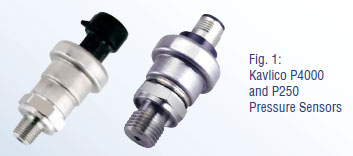 Piezo-Resistive
based sensors such as the Kavlico P4000 and P250 (Figure 1) use
welded oil filled headers with stainless steel isolation
diaphragms to protect the sense technology. Piezo-Resistive
based sensors such as the Kavlico P4000 and P250 (Figure 1) use
welded oil filled headers with stainless steel isolation
diaphragms to protect the sense technology.
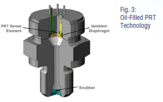
(Figure 3) is a cross section of the pressure media interface
for that type of product. The sense element is a high pressure
3,000 to 6,000 PSI piezo-resistive silicon MEMS device (PRT).
The PRT device consists of 4 resistors connected in a Wheatstone
Bridge configuration. It is mounted on a header
with glass feed-throughs for the external connection to the
leads of the silicon chip. The header is welded into a stainless
steel housing with an isolation diaphragm. The header structure
is filled with silicon oil and then sealed. As pressure
is applied against the diaphragm, it is transmitted to the
element by the incompressible oil. The MEMs device provides an
output proportional to pressure that can be amplified and
conditioned by an ASIC inside the sensor body. The structure can
be made more robust by adding a pin hole sized snubber of the
pressure spikes by providing a restriction followed by an
expansion chamber inside the thread in front of the diaphragm.
These types of pressure sensor are optimized for pressure
ranges between 1,000 and 5,000 PSI and are appropriate for less
price sensitive medium to lower volume applications.
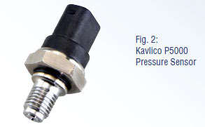 Higher
volume and higher pressure applications are serviced by thin
film technologies such as those found in the Kavlico P5000
(Figure 2) series. The cross section of a thin film unit is
shown in (Figure 4). A stainless steel piece is hollowed out to
provide a thin diaphragm and materials are deposited on the top
of that piece of steel. Resistors are implanted into the thin
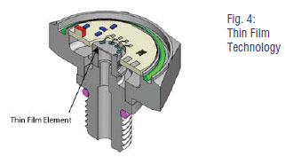
film in a Wheatstone Bridge arrangement and the pressure Higher
volume and higher pressure applications are serviced by thin
film technologies such as those found in the Kavlico P5000
(Figure 2) series. The cross section of a thin film unit is
shown in (Figure 4). A stainless steel piece is hollowed out to
provide a thin diaphragm and materials are deposited on the top
of that piece of steel. Resistors are implanted into the thin
film in a Wheatstone Bridge arrangement and the pressure
applied to the hollowed out side of the steel is transferred to
those resistors, upsetting the bridge. The thin film elements
are welded into stainless steel housings and appropriate signal
conditioning is added to complete the sensor construction. It is
not uncommon to find thin film elements rated as high as 20,000
PSI which would be impractical in other sensor technologies.
 The
electrical, temperature and stability performance of the product
is defined by the materials used. The unit output is smaller
than that of a comparable silicon PRT structure and must be
amplified to a usable output voltage range. Nickel The
electrical, temperature and stability performance of the product
is defined by the materials used. The unit output is smaller
than that of a comparable silicon PRT structure and must be
amplified to a usable output voltage range. Nickel
Chromium films are widely used by many suppliers. Newer Titanium
Oxynitride (TiON) films used in the P5000 provide almost twice
the electrical output per applied pressure as more conventional
materials allowing for higher stability underhigh temperature
operation.
There is no single best approach for all hydraulic pressure
sensing applications. Maximum pressure range, cost targets,
physical size, output configuration, safety considerations and
temperature range are all factors that must be evaluated in any
system design.
For more information contact:
Kavlico
14501 Princeton Ave., Moorpark, CA 93021
Tel: (805) 523-2000 – Fax: (805) 523-7125
Web: www.kavlico.com – E-Mail:
sales@kavlico.com
|
|
|
|
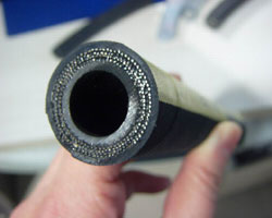 How
Long Should Hydraulic Hose Last? How
Long Should Hydraulic Hose Last?
By Jack Weeks
GPM Hydraulic Consulting, Inc.
How long should the hoses in a hydraulic machine last? Well, the
short answer is that it depends. Some people are surprised to
find that hose material has a shelf life and that it can be
affected by factors such as temperature, humidity and
ultraviolet light exposure of the area where it is stored. This
differs by hose type and manufacturer of course, but that is not
what our customers usually mean when they ask about hose life.
When a hose is replaced on a hydraulic machine, we would like to
know about how long we can reasonably expect this hose to stay
in service.
Unfortunately, hose life can be very hard to predict. There are
simply too many variables between machines to make any sort of
blanket statement. But if you find yourself changing the same
hose over and over again while the other hoses on the machine
seem to be immortal, it is definitely time for some further
investigation to determine what deteriorating factors are
affecting that particular hose and not the others.
Naturally hoses will not last forever. And certainly they will
not last as long as hard pipe. Wherever possible, long hose runs
should always be replaced by hard pipe, terminating with a
length of flexible hose into.components to absorb shock. But
some applications demand hoses and we would like for them to
last as long as possible. So even if we can't predict hose life
with any accuracy, we can at least be sure that we get the
maximum possible life from the hose. Here are a few of the most
common mistakes we find that can shorten hose life expectancy:
Using the wrong size hose. Sizing the hose is more than cutting
it to the right length and putting on the right fitting. Hoses
are designed for specific flow rates, pressures and
temperatures. If we deviate from their specifications, hose life
can suffer. While that statement may appear blatantly obvious,
we often find that hose specifications have been ignored -
sometimes inadvertently and sometimes deliberately. Most plants
stock hose in various diameters but not of different
characteristics. Sometimes this one-size-fits-all approach gets
us in trouble, particularly when a new machine is installed that
requires hose with different specs. The same hose that is used
everywhere else in the plant eventually gets used on this new
machine with disastrous results. Since there is only one type of
hose in stock, no one is likely to check to see if it suits the
needs of the machine - it has to, that's the only one we have!
Sometimes the wrong hose is deliberately installed. We have seen
hose that is too small in diameter installed in an attempt to
make the machine run faster. A common misconception is that
smaller diameter hose results in a higher flow rate. Higher flow
rate, of course, does increase speed. The problem with this plan
is that a higher flow rate cannot be obtained by undersizing
pipes or hoses. Hose diameter affects fluid velocity, not flow
rate. No matter how small the hose, if you put 10 GPM into it,
you can get no more than 10 GPM out of it. Increasing the
velocity will however add heat and turbulence to the machine.
Not only will this damage the inner metal tube (especially at
bends), it can also cause premature failure of hydraulic
components in the machine. At one plant, the technician was so
insistent that we were incorrect about this that he timed the
movement of the actuators in the machine. They did in fact move
faster than they had with the correct larger hose. Only once we
pointed out that the system temperature had increased by 37oF
did he understand the real reason the speed had increased. He
could have had exactly the same speed increase (without the
additional turbulence) by turning up his oil heater. Yet he was
horrified at the suggestion of doing this! As well he should be
- whenever the speed of a machine can be increased by raising
oil temperature, there is an orifice that can be opened instead.
But that's a different article.
Some people over size hoses as well. This in an an attempt to
keep fluid velocity and temperature at a minimum. There is merit
to this, but also a point of diminishing returns. As long as
your hose meets the requirements of the system, you will
probably not get enough benefit to justify the cost of the
larger hose. Add to that the problem of making a larger hose fit
the application, causing bends at the fitting and increasing the
chance of the hose rubbing on another surface or another hose
and suddenly oversizing our hoses no longer sounds like such a
great idea.
Often hoses are cut too long for the application. When we
replace a single hose, we want to be sure we have enough hose so
we only have to do it once. So the tendency is to cut the hose
longer than we need. Thus hoses tend to "grow" over a period of
time. In our hydraulic classes, we teach that most hoses (with
exceptions of course, such as traveling cylinders) should be no
longer than about four feet. But this is not set in stone - by
and large, a little common sense can prevail here. Most of the
time, if a hose installation looks good, it is good. But if the
hose is rubbing against something, snaking around the floor, has
unnecessary bends or is jammed into too small of a space,
perhaps it needs some attention.
Failing to take into account the abuse a hose will suffer. Hoses
are not indestructible. They should not be installed in such a
manner as they are likely to be stood on, run over by a forklift
or rub against another hose or surface. If subjection of a hose
to a hazard is unavoidable, there are many options available to
protect it. If a hose must be installed close to a heat source,
for instance, a metal heat shield should be installed to protect
it. If abrasion cannot be avoided, use a protective cover.
Ultraviolet rays from the sun can badly degrade hose material,
so if it must be subjected to the elements, protect it.
Just as water and other contaminants in hydraulic oil can damage
components, so can they damage hoses. And whenever we have a
choice between installing a hose to run vertically or
horizontally, the horizontal installation will cause less pull
on the hose fittings.
Forgetting about shock spikes when specifying hose. All too
often, we have seen hoses installed that are underrated. A
machine that operates at 1500 PSI should not have hose rated for
only 2000 PSI. It is not uncommon at all for shock spikes to
reach several thousand PSI above the operating pressure of a
machine. The OEM can recommend the proper hose pressure rating.
And if we use the OEM recommended hose, be sure we set the
system pressures to the OEM recommendation as well. A pressure
setting that is 200 PSI too high will result in shock spike
increases of much more than that. Keep shock spikes to a minimum
by making sure the pressures are set correctly and keeping
components that absorb shock in good repair.
Using an incompatible hydraulic oil. All hydraulic oil is not
the same. A wide range of additives is available. Before trying
a new oil, be sure to ask your oil vendor if it could damage the
hoses.
Neglect. An inspection of all of the hoses should be performed
at least monthly. Signs that a hose is about to fail such as
bubbling of the outer hose, loss of flexibility, cracks,
discoloration or signs of abrasion are easy to spot. It is
always better to replace the hose before it fails. If the hose
fails during production, not only will production time be lost
but it is likely that the ruptured hose will damage something
else. Anyone who has ever witnessed a hydraulic hose breaking
knows that it is not something to be taken lightly. Tremendous
force is released (and a lot of hot hydraulic oil). If your
hoses have lasted a year or two, consider yourself fortunate and
replace them whether they appear to need it or not. And if a
hose is located where someone could be injured or killed if it
fails, a much closer change interval is justified.
Jack Weeks entered GPM’s organization in January of 1997 as a
CAD draftsman and hydraulic instructor. He has trained thousands
of electricians and mechanics in Hydraulic Troubleshooting
methods. His computerized animations have made GPM's
presentations and training CD's the recognized leader in the
industry. He received his education from the Georgia Institute
of Technology School of Electrical Engineering and the
Department of State Foreign Service Institute. Jack is an
experienced draftsman and taught telecommunications equipment
operation and repair for the Central Intelligence Agency at
American embassies overseas.
GPM Hydraulic Consulting, Inc.
Box 1376
Monroe, GA 30655
(770) 267-3787
www.gpmhydraulic.com
|
|
|
|
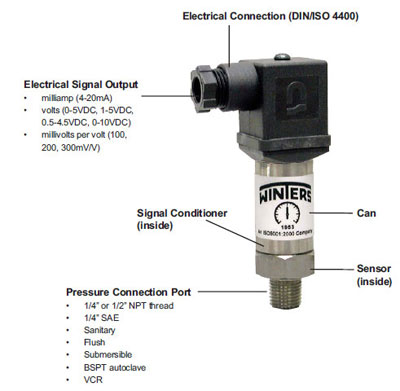
Selecting a Pressure Transmitter
Selecting the correct pressure transmitter for the appropriate
application can be a complex task, and failure to do so can make
the operation of the equipment ineffective and possibly
hazardous. Please read below to gain a better understanding of a
transmitter’s various components and parameters.
Transmitters can be thought of as electronic pressure gauges.
There are two kinds of electronic pressure gauges: pressure
transmitters and pressure transducers. The general difference
between a transmitter and transducer is the electrical output,
where a transmitter outputs signals in milliamps (mA) and a
transducer outputs signals in volts (V) or millivolts per volts
(mV/V).
 The
two primary areas to focus on when selecting a pressure
transmitter are the operating conditions (environment) and
performance requirements. The
two primary areas to focus on when selecting a pressure
transmitter are the operating conditions (environment) and
performance requirements.
Operating Conditions
Knowing where the transmitter will be operating in and choosing
accordingly the transmitter case and wetted materials will
extend its service life. Each transmitter should be selected
partly on the basis of the medium being measured. Ensure that
the parts exposed to the medium are compatible with or can
withstand its particular characteristics.
Keep in mind that heavy vibration, shock, moisture and electric
interference will affect pressure sensing. Since each
application is specific to a certain set of requirements,
understanding the application’s needs will determine the model
required.
Extreme temperature ranges can also produce adverse effects to
reading accuracy. Make sure you identify an acceptable
temperature effect on span (thermal drift) when selecting your
transmitter. These can be as low as 0.2% FSO per 10°K.
If the transmitter is installed for outdoor use, ensure that the
appropriate type of enclosure/seal is selected. All of Winters’
pressure transmitters are sealed against water and dust entry,
and meet standard NEMA enclosure ratings. Standard housing is
304 or 316 series of stainless steel.
Performance Requirements
Is the pressure range being measured in the positive or vacuum
scale of measurement? Is each point of measurement stand-alone
or are the differences between two points being measured
(differential)?
In general, pressure transmitters provide highly accurate
pressure readings. It is important, however, to always choose a
range that is suitable to your requirements. Consider this
scenario: a transmitter that has an operating range of 0 to
200psi and has an accuracy of +/-0.25% is being used to measure
pressure on a piece of equipment that only goes to a maximum of
20psi. An accuracy of +/-0.25% over a 200psi range means that
the maximum error you may see is +/-0.5 psi. Therefore, for a
measurement output of 7psi, the real number may be between 6.75
to 7.25psi. An error of 0.5psi means you have selected a
transmitter with an error of 7.14% (0.05 divided by 7) at 7 psi.
So, select a transmitter that has the closest normal operating
range to what you are measuring, and consider an acceptable
accuracy percentage.
Also, be sure about the type of output you need. Winters’
standard transmitter outputs are in milliamps. Output in volts
is available.
How Transmitters Work
Power is supplied to the circuit and the flow is regulated.
1. Pressure pushes on a sensor
2. The sensor flexes and changes the resistance or capacitance
of a circuit mounted on the backside of the diaphragm (the
change in the flow of electricity across the circuit is in
direct proportion to mechanical force/pressure applied to the
diaphragm)
3. Special electronic circuitry conditions and amplifies the
sensor’s signal and converts (transduces) it to a useable signal
(i.e. 4-20mA)
4. Electrical output signal is sent to an indicator or computer
Winters Instruments
121 Railside Road, Toronto, ON M3A 1B2
416-444-2345 / 1-800-WINTERS /
www.winters.com
|
|
|
|
Company Continues to Refine Hydraulic Hybrid Drives For
Refuse Vehicles
CLEVELAND, OHIO - Parker Hannifin Corporation, the global leader
in motion and control technologies, continues to refine the
company’s new hybrid drive technology, which is an advanced
hydro-mechanical series drive system designed to significantly
reduce fuel consumption and increase productivity in vehicles
with high start-and-stop applications.
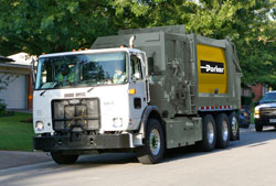 Parker’s
hybrid drive system for refuse trucks replaces a vehicle’s
conventional transmission with a series hybrid drive system that
marries the variable features of a hydrostatic drive, which is
ideal for urban routes, with the efficient performance of a
mechanical drive that performs best at highway speeds. Coupling
this unique hybrid drive system with brake energy recovery
technology provides the ideal solution for severe duty
applications. Parker’s
hybrid drive system for refuse trucks replaces a vehicle’s
conventional transmission with a series hybrid drive system that
marries the variable features of a hydrostatic drive, which is
ideal for urban routes, with the efficient performance of a
mechanical drive that performs best at highway speeds. Coupling
this unique hybrid drive system with brake energy recovery
technology provides the ideal solution for severe duty
applications.
The main benefits of the Parker hybrid drive system are fuel
savings, reduced emissions, and dramatically reduced brake wear.
Refuse vehicles equipped with Parker’s hydraulic hybrid drive
system have achieved fuel savings of 30% to 50% during track
testing and actual field trials of refuse collection cycles.
Vehicles can utilize full engine power at any time, but the
system’s design optimizes efficiency by matching engine load
with vehicle requirements. Reduced fuel consumption, a
corresponding reduction in emissions, substantially reduced
brake wear and improved off-the-line acceleration are all
benefits of the Parker hybrid drive system.
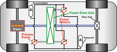 Parker’s
hybrid drive system is built around the company’s proprietary
Power Drive Unit (PDU), designed specifically for high power,
high start-and-stop applications. An onboard controller
coordinates pumps, hydrostatic motors and accumulators to power
the vehicle when in hydrostatic mode during start-and-stop
operation while collecting refuse. Instead of solely using power
from the diesel engine, accumulated energy from the vehicle’s
braking system is stored and used to power the truck each time
it accelerates. As the truck reaches highway speed, the PDU
transfers from hydrostatic drive to mechanical drive to maximize
operational efficiency. Parker’s
hybrid drive system is built around the company’s proprietary
Power Drive Unit (PDU), designed specifically for high power,
high start-and-stop applications. An onboard controller
coordinates pumps, hydrostatic motors and accumulators to power
the vehicle when in hydrostatic mode during start-and-stop
operation while collecting refuse. Instead of solely using power
from the diesel engine, accumulated energy from the vehicle’s
braking system is stored and used to power the truck each time
it accelerates. As the truck reaches highway speed, the PDU
transfers from hydrostatic drive to mechanical drive to maximize
operational efficiency.
The application of Parker’s hybrid drive system for refuse
trucks is an excellent fit. Based on intelligence gathered from
refuse companies, fleet owners, municipalities, and original
equipment manufacturers, Parker identified the need for
improvements in fuel efficiency, emissions, drivability, brake
wear, and overall productivity. The new Parker hybrid drive
system is tailored specifically to meet these demanding refuse
industry needs.
Since the system’s inaugural showing at the 2006 Waste Expo show
in Las Vegas, Parker has continued to refine the hybrid drive’s
packaging, components, and control strategy to optimize system
performance and reliability for refuse collection vehicles. The
latest version, featuring an innovative, patent pending design
for packaging mechanical, electric, and hydraulic components,
will be unveiled at the WasteExpo 2009 Exhibits, June 9 – 11 at
the Las Vegas Convention Center, Las Vegas, NV.
Parker’s disciplined, stage gate product development process
integrates computer modeling, dynamometer testing, lab testing,
and full vehicle on-road operation to validate system
performance per customer criteria such as functionality,
quality, reliability and added value.
While much of the development and validation of the hybrid drive
system is performed within Parker’s engineering offices and labs
around the globe, there is no substitute for on-road vehicle
evaluation. Currently, Parker is evaluating prototype vehicles
through a variety of acceptance tests that replicate real-world
operation. A state-of-the-art vehicle proving ground contains
all road and driver conditions required to validate vehicle
drive performance and durability. Trucks are operated 24/7 in a
controlled environment with professional drivers, mechanics, and
fleet managers evaluating fuel economy, acceleration, braking,
responsiveness, road loads, vibration, gradability, and other
conditions that are encountered in refuse collection service.
“Based on the feedback we’ve received to date, we are confident
that Parker’s advanced series hydraulic hybrid technology has
real potential to significantly improve the fuel efficiency,
productivity, and environmental footprint of refuse and similar
heavy trucks across the globe,” said Vance Zanardelli, Manager
of Parker’s Energy Recovery Business.
In addition to hybrid drive systems for refuse collection
vehicles, Parker is also developing variations of the hybrid
drive to meet the needs of other on- and off-highway
applications. Parker is using the technologies developed for the
refuse program as building blocks for configuring solutions
tailored for other vehicle platforms with high start-stop duty
cycles that also require significantly different torque and
packaging solutions. Parker’s broad array of motion and control
technologies provides the flexibility required to configure and
control these multiple application drive solutions.
For more information about Parker’s Hydraulic Hybrid Drive
System, visit
http://www.parker.com
|
|
|
|
Harvesting the Energy of Leadership and Innovation
Within Our Education System.
The Productivity Revolution That Puts People at Center
Stage.
By Larry Davis, President, Daman Products
Teaching core subjects in isolation.
As a society, we are not equipping our children with the
competitive advantages necessary to prosper in the productivity
revolution that is occurring. A revolution that puts people, not
equipment, at center stage.
A revolution that can have a dramatic impact on productivity in
the private, government, service, and education sectors. This is
a process that has emerged in the manufacturing arena and is
slowly spreading to other sectors. Ironically, it has little to
do with manufacturing.
A number of events have come together to create a conflux of
thought on the subject of education, not the least of which are
the inordinate amount of time spent in our public schools
policing behaviour, and an unacceptable dropout rate. At the
heart of the matter are the teaching/training institutions in
our society and how they approach teaching: teaching core
subjects in isolation. Our schools’ preoccupation with passing
state tests is likely exacerbating a singular focus on core
competencies. At the technical school level, we teach math,
blueprint reading, welding, machine technology, and other
technical skills. Our state government, through Workforce
Development, provides grant money to industry for teaching these
“portable” skills.
These necessary and traditional skills are portable in a narrow
sense; however, there is a growing demand for another kind of
skill set – skills that are not found naturally in our schools,
family units, or traditional business models. These are
necessary skills required in addition to core competencies, and
in conjunction
with technical skills that will make our society geometrically
more productive and competitive as we are progressively exposed
to the threats and opportunities of a global economy. The sum of
our experiences leads us to ask if we should look internally
(within our businesses, service providers, governmental
institutions, and educational systems) for answers to our
perceived loss of worldwide competitiveness.
In order to set the stage, it is important to explain the
context for these thoughts. Our company is what is considered an
advanced manufacturing company. To the surprise of many, this
does not mean that we are technically superior, or have the best
and newest equipment, nor does it mean that we have replaced
humans with
robots. What it does mean is that we have redesigned the
workflow of our business to move effectively, while we continue
to improve the process through iterations and refinements. This
may sound logical and not newsworthy. On the contrary, this is
unusual and counterintuitive to many institutions. For example,
business world fundamentals such as forecasting systems, some
business software, cost accounting, and purchasing can actually
introduce chaos into operations. Traditional business,
education, service industry and government work models are
fraught with waste and redundancy because we have been
conditioned to work around mistakes and inefficiencies. Most
managers will tell you they are glorified “firefighters.” They
operate in a reactive mode instead of being proactive. We were
in this situation in 1997. The simplified changes we have made
since 1997 have allowed us to improve our productivity by 25
percent by making “environmental” changes, with virtually no
machine technology improvements.
So what is different if productivity is not the result of
conventional technological investment?
For a moment, imagine a work environment in which the
“supervised” employees were free to manage their days without
supervisory input. They decide who should run which machine, not
a scheduler. They are responsible for training new people who
join the company, not the training department. They receive
material into their work area, not the receiving department.
They decide when to take breaks and lunch, not their supervisor.
They initiate purchase orders for tooling from the shop floor
and virtually bypass the purchasing department, and receive
those tools into inventory. They schedule their vacations, not
the personnel department. They perform preventive maintenance on
their equipment, not the maintenance department. They determine
when it’s time to build parts, not someone forecasting product
demand. They determine who needs help and provide it, not their
foreman. All of these events are doable without the direct
involvement of a supervisor or other management personnel. This
environment gives people control over their work environment and
is the opposite of the typical “command and control” methods of
most institutions.
What I have just described is so far from conventional thinking
that it may seem absurd. The fact is that this is precisely the
path our company chose. It hasn’t been an easy path to blaze, as
most of us were not raised or educated in fundamentals that are
essential for productive teamwork.
The magic of team competencies.
The magic lies in training our people to work comfortably within
teams, to teach leadership and communication skills, and to
think creatively. This is certainly easier said than done, but
imagine a work environment where people are comfortable leading
meetings, using brainstorming and problem-solving techniques
when encountering problems, have the ability to reason and find
information, and are comfortable giving and receiving feedback.
We call these skills “team competencies.” In short, these are
simply leadership and communication skills, and affectionately
considered “soft” skills. The problem with the term “soft” is
that it implies something less important than “hard” skills. I
believe they are at least equally important and, arguably, soft
skills are more universally applicable and the foundation upon
which future competitive advantage will be gained.
With team competencies in place, our people have been given
uncommon accountability and responsibility to accomplish their
work. We have effectively unshackled their minds and engaged
their brains, unlike most traditional operating models where
work is accomplished per the boss’ instructions. This new model
has been incredibly effective in increasing our competitiveness.
Imagine what a 25 percent boost in U.S. productivity would mean
in terms of our global challenges.
The value of training in mainstream education.
Here’s the rub: Finding people who are prepared properly for
this environment is difficult. Other companies that have made
the same improvements state that they will, on average,
interview 100 people before finding someone who exhibits the
values and traits suitable to this environment. This expends a
great deal of time and energy in the hiring process and inhibits
companies from keeping up with product demand. Additionally,
in-plant training to bring new people up to speed on our methods
requires even more resources. We recognize the value of this
training and are more than willing to commit to this investment
in our new people. But imagine the competitiveness that would
result in this country if what we were teaching our people was
readily taught in our learning institutions. Instead of this
being an anomaly, what if it were part of mainstream education?
In my opinion, these types of soft skills are much more valuable
to this nation’s workforce. Where welding skills will allow an
individual to find another welding job, soft skills will allow
people to move in and out of industries.
Imbedding “soft skills” and the need for educational change.
What have we learned? In teaching team and leadership skills, we
have found that the most effective method is to relate the
training to solving a real problem. Training based on
hypothetical situations is most often time wasted. Bringing a
team together around a common problem, and introducing
techniques to understand and solve the problem, has been
powerful. We have seen shift workers, who in the past would not
speak to one another, leave a group training session with hope
that there was a likely solution. In this setting, the teams had
a real need for learning skills, and reinforce the power of
those skills by solving their issues.
If this is valuable learning, how do we introduce it into our
educational system? We believe it starts with a dialogue, simply
suggesting that our current system is in need of change. I can
speculate that the change will be difficult and that “teaching a
class” in soft skills will not get the job done. Soft skills
have to be imbedded in the entire curriculum, and will require
major paradigm shifts in teaching philosophy and in the way our
educators are educated. A new system would aspire to encompass
core skills learning in conjunction with team and leadership
building. This may require classes that no longer are identified
as “math,” “science” and “history,” but are instead rolled into
multidisciplinary classes where teachers work jointly to coach
and mentor students as they research subject matter to solve
multidimensional problems. We believe that even as our employees
are activated and energized by our trust and investment in them,
so will our students be engaged when they become active
participants in their own education and realize that learning
can be rewarding and exciting, as can the workplace. Learning
and success can be infectious, and this new approach to
education may just be the way to stimulate the process. We have
also learned that significant improvement does not happen
through an evolutionary process, but instead through the
deployment of disruptive technologies or, stated another way,
major system change. Nibbling around the edges of our current
educational system will, at best, generate incidental change.
As more businesses realize the benefits of abandoning the
command and control models, the need for intelligent people with
solid team competencies is going to grow. As a society, we are
not preparing our children to prosper in this competitive
team-oriented business model.
Daman provides outstanding technological and service leadership
beyond customers’ expectations in order to promote their
interest, thereby ensuring continuous opportunities for Daman
employees. This philosophy statement drives the organization. As
a result, Daman has developed a solid reputation as one of the
best suppliers customers have. Each Daman team member is driven
to provide long-term, reliable service that exceeds customer
expectations. Daman offers a complete line of hydraulic valve
manifold products comprised of two basic groups: Custom
Engineered Products and Standard Products. All components are
manufactured to tolerances that meet or exceed National Fluid
Power Association (NFPA) as well as the International Standards
Organization (ISO) specifications. Daman has created a
streamlined system for estimating, engineering, and
manufacturing Custom Engineered Products from as little
information as a hydraulic schematic and component bill of
materials. Daman has also developed the most comprehensive
catalog of Standard Manifold Products in the world. Our product
lines provide every customer with more than one million choices
to refine and enhance their hydraulic system, ranging from ISO
02 valve patterns through ISO 10.
www.daman.com
|
|
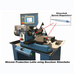 CASE
STUDY LOWER COST PRODUCTION LATHES ARE BEING USED AS AN
ALTERNATIVE TO CNC MACHINES IN MANY SMALL PARTS PROCESSING
OPERATIONS CASE
STUDY LOWER COST PRODUCTION LATHES ARE BEING USED AS AN
ALTERNATIVE TO CNC MACHINES IN MANY SMALL PARTS PROCESSING
OPERATIONS
Modern production lathes are increasingly being used in place of
costlier, more complex CNC machines for many part processing and
second operation applications. Advancements in this technology
enable production runs numbering in the thousands to be
performed more quickly, with less operator skill while offering
longer cutting tool life.
The McLean (3) axis production lathe is an example of production
lathe design that fulfills this promise. Setup and programmed
automation for each job is achieved via a touch screen which can
store programs for easy change from one part or operation to
another. The McLean system allows each of its optional (3) slide
mechanisms to work in virtually any combination to perform
grooving, chamfering, boring, drilling and other basic “CNC”
type production chores. The slides may be programmed to work
individually in any sequence, or any two, or all three to work
simultaneously. Each slide is air powered. The feed rate is
hydraulically controlled by a Deschner Kinechek® speed regulator
incorporated in each slide mechanism to provide precise,
infinitely adjustable feed control. The Kinechek hydraulic speed
regulator built into the slides on the Mclean production lathes
assure the cutting tool will move smoothly while the part is
being machined to provide a fine finish and prolong cutting tool
life.
The McLean production lathes may be considered as a more
affordable alternative to CNC machines for many types of
applications.
Contacts: Deschner Corporation
3211 West Harvard Street
Santa Ana, CA. 92704
E info@deschner.com
T 714 557 1261
www.deschner.com
|
Cartridge Style Power Steering Valve (Load Sensing Flow
Control Valve)
The power steering valve, which is well known outside the
cartridge valve industry, is asimple priority type spool valve,
combined with a remote load sensing orifice, used forprecision
flow control on demand. Up until recently, all Priority On
Demand Spool (PODS) valves were large, heavy, cumbersome, cast
iron valves with ports that were fixed in size and location.
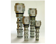 In
an effort to advance cartridge valve technology, Command
Controls Corp. has introduced a small, lightweight, flexible,
cartridge style PODS valve, which can be designed into just
about any circuit or any size manifold requiring
priority-on-demand. This type of valve, even though it has been
in use for over forty years, commands even more attention than
ever, due to rising energy costs. In
an effort to advance cartridge valve technology, Command
Controls Corp. has introduced a small, lightweight, flexible,
cartridge style PODS valve, which can be designed into just
about any circuit or any size manifold requiring
priority-on-demand. This type of valve, even though it has been
in use for over forty years, commands even more attention than
ever, due to rising energy costs.
The load sensing flow control is used on many applications,
especially power steering circuits where priority flow is
needed. The valve functions in all systems: open center, closed
center and load sensing. It provides flow and pressure to a
controlled circuit on
demand. A fluid linked power steering system is used for this
illustration, but the same principles can be applied to any
circuit requiring a load sensing four-way valve.
A known performance characteristic in both an open and closed
center hydraulic system is that the flow rate is affected by the
resistance of the load, when a valve is opened to move the load.
However, with a load sensing flow control valve, the flow will
depend on the amount the valve is opened, independent of the
load. By sensing the load, pressure demand is compensated, and
the flow rate is actually insensitive to load. Therefore, the
flow and the pressure in the controlled circuit, provided by the
pump, will only be what is needed to move the load, plus a small
amount for control. Any surplus pump capacity is usable in other
circuits. In short, a load sensing system provides maximum
energy savings.
In a load sensing system, such as the one mentioned above, the
load sensing priority valve is typically used to give priority
to steering and braking. In each case, the same load sensing
hydraulic flow control is used, and the function remains the
same. Maximum energy savings can be achieved by using more than
one priority valve for more than one stage of priority. This
allows for a multi-circuit system with the use of only one pump
– a significant cost reduction!
The load sensing, flow control valve can function to build
pressure or reduce pressure to the controlled circuit, as
needed, in any type of system. It also gives priority to the
controlled flow circuit as needed without cutting off flow to
the excess flow circuit. The controlled flow circuit relief is
set lower than the main system pressure, so that the controlled
flow circuit can hold relief pressure, while the excess flow is
still available up to the maximum system pressure. The
controlled flow circuit relief will also limit the controlled
flow circuit pressure, should the system pressure exceed the
controlled circuit relief setting. This is especially true in a
closed center system, where the system pressure could be set at
350 bar (5000 psi), while the
steering circuit is limited to 70 bar (1000 psi).
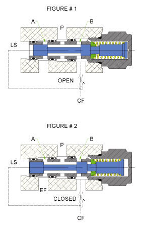 Let’s
consider the operation with a fixed displacement pump. When
there is no flow from the pump, the spring will move the spool
to the right until it engages the stop. The “P” port will then
be open to the “CF” controlled flow port and the “EF” excess
flow port will be closed. Now, consider the controlling orifice
closed when the pump is started. Inlet flow will now enter at
the “P” port and exit at the “CF” port. However, with the
orifice closed, the only open passageway is to the closed end of
the spool. The inlet flow pressure will then move the spool
against the bias spring until port “EF” is open, and all of the
flow will exit at this port as excess flow. This flow will be
from port “P” to port “EF” with a pressure drop (rP) of 7,0 bar
(100 psi), as determined by the bias spring. Let’s
consider the operation with a fixed displacement pump. When
there is no flow from the pump, the spring will move the spool
to the right until it engages the stop. The “P” port will then
be open to the “CF” controlled flow port and the “EF” excess
flow port will be closed. Now, consider the controlling orifice
closed when the pump is started. Inlet flow will now enter at
the “P” port and exit at the “CF” port. However, with the
orifice closed, the only open passageway is to the closed end of
the spool. The inlet flow pressure will then move the spool
against the bias spring until port “EF” is open, and all of the
flow will exit at this port as excess flow. This flow will be
from port “P” to port “EF” with a pressure drop (rP) of 7,0 bar
(100 psi), as determined by the bias spring.
If we want flow in our controlled flow circuit (priority flow),
the controlling orifice of the steering wheel is opened. If
there is no load (zero pressure) downstream of the orifice, and
there is a 7,0 bar (100 psi) pressure upstream of the orifice
(determined by the bias spring), then the flow in this circuit
will be that which can be pushed across the orifice by a 100 psi
delta P.
Now consider that the controlling orifice is open, but the load
passageway is blocked downstream. The pressure at port “CF”, 7,0
bar (100 psi), can pass through the orifice, and to the spring
end of the spool, to add to the force at the left end of the
spool. The spool will now move to the right, to close off port
“EF” at port “A”. With the controlled flow circuit blocked,
there is no flow across the orifice, and the pilot pressure at
both ends of the spool is identical. The spring force will now
hold the spool to the right, regardless of how high the pressure
rises. As such, the circuit now has priority. Pressure will
continue to rise until the relief setting of the pump is
reached, and the flow will spill over the relief valve and go
back to the tank. There will be no flow at port “EF” and no flow
at port “CF” with the circuit blocked. If the controlled flow
circuit is not blocked, but is opened to a load that will move
at, for example, 100 bar (1500 psi), the action will be the same
up to 100 bar (1500 psi). In other words, the 7,0 bar (100 psi),
caused by the spring, will pass through the orifice and to the
load sense “LS” pilot line to the left end of the spool, and
will cause pressure build up until 100 bar (1500 psi) is
reached. At this point, the load will start to move. With flow,
there will also be a pressure drop across the orifice. The
pressure will continue to rise and move the load until the flow
through the orifice causes a pressure drop across the orifice
equivalent to the bias spring setting, which in this case is 7,0
bar (100 psi). The flow will then level off at this setting, and
the pressure will vary as needed.
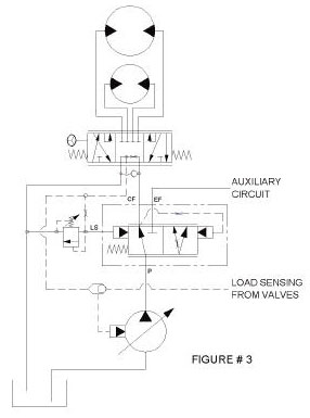 In
the active mode, the spool is balanced between the forces at its
ends. Restated, the force of the bias spring must be reacted by
the pressure difference at its ends, which is In
the active mode, the spool is balanced between the forces at its
ends. Restated, the force of the bias spring must be reacted by
the pressure difference at its ends, which is
caused by the pressure drop across the controlling orifice. Load
pressure can also act on both ends of the spool, so the
difference in pressure caused by orifice, is the only pressure
that is effective to control the flow rate. Flow rate in the
controlled flow circuit will be according to the orifice area,
and the delta P caused by the bias spring regardless of load.
Lastly, consider a load being applied to the Excess Flow
(secondary or auxiliary) circuit, while no load, and only flow,
is applied to the Controlled Flow (primary) circuit. The flow
rate in the primary circuit will be as determined by the orifice
area, and the 7,0 bar (100 psi) bias spring setting. When the
load in the secondary circuit exceeds 7,0 bar (100 psi), the
pressure at the controlling orifice will start to exceed 7,0 bar
(100 psi) and the flow rate will tend to increase. However, the
pressure at the right end of the spool will also increase, and
move the spool to the left. The control has now switched from
“A” to “B”. “A” will now be wide open or non-controlling, while
the restriction at “B” will reduce the pressure, and
consequently the flow in the primary circuit. The pressure and
flow in the primary circuit will remain almost unchanged by the
loads in the secondary circuit. Any change that occurs will be
the result of the difference in the bias spring force, which is
caused by the change in length as the spool moves to close off
“B”. The spring force changes slightly during all control
whether the control is at “A” or “B”. It is important to note
that when the load in the secondary circuit exceeds the bias
spring setting, which is 7,0 bar (100 psi), the restriction at
“A” is very low; it is basically a passageway loss. With a fixed
displacement pump and an open center system, this means that
there will always will be a 7,0 bar (100 psi) pressure drop from
port “P” to port “EF”, but once the load in the secondary
circuit exceeds this pressure drop, it is very low, and is on
the order of line and fitting losses. Any bank of valves, along
with lines, fitting and filters in the secondary circuit, will
probably cause a load large enough to shift the spool, and the
through flow pressure loss in the valve will be very low as
well. If the load in the secondary circuit is high, or the
circuit has blocked the pump pressure, it will rise to the
relief setting, while the pressure in the primary circuit at
port “CF” will still be at 7,0 bar (100 psi). The flow in this
circuit will still remain as determined by the spring force and
the orifice area, and the pressure and the flow will be
restricted at “B”. Or, if there is a load in the primary
circuit, the pressure will rise as needed, while the flow rate
will be unaffected by the load in either circuit. Note that this
same condition exists in a closed center system with a pressure
compensated pump, but instead of flow being forced over a relief
valve, the pump de-strokes at a high operating pressure. In the
area of the load sensing flow control, and in the primary
circuit, the operation is identical whether it is in an open or
closed center system. The primary circuit also functions the
same with a load sensing pump, pressure compensated pump or a
fixed displacement pump.
In summary, the advantages of the load sensing flow control
valve (PODS valve), when used in a fluid linked power steering
system or other similar system are: 1) only the flow demanded by
a steering maneuver, by the vehicle operator, goes to the
steering circuit; 2) the steering function has priority over
other functions in the system; 3) flow not demanded for steering
is available to other circuits; 4) improved steering control
exists regardless of the steering load pressure; and 5) four
sizes are available with regulated flows up to 30 gpm (115 lpm).
- - -
Written by Connie Kosarzecki of Command Controls Corp., Elgin,
Ill. Kosarzecki has worked in the fluid power industry since
1958. Command Controls Corp, established in 1993, manufactures a
complete line of state-of-the-art, high-pressure (5,000 psi/350
bar), high-performance, screw-in, cartridge-type, hydraulic
control valves and manifold systems for the fluid power
industry. For more information, please visit
www.commandcontrols.com.
|
Wide Range Temperature, Pressure, and Fluid
Resistant Hydraulic Cylinder Sealing Systems
Joel Johnson Ben Westbrook
Simrit Division of Freudenberg-NOK
Noriyuki Matsui
NOK Corporation
ABSTRACT
Excessive temperature and fluid compatibility
often create problems for hydraulic cylinder
sealing. Overall, new materials and designs are
necessary to meet the increasing
requirements of the industry. Smaller packages
with higher pressures combined with hotter
ambient temperatures (often directly linked to
new environmental standards)
continue to drive the demands for better
performing seal systems. The new advancements
presented in this paper help the fluid power
engineer design a more robust
cylinder that can be used in a wide variety of
applications while providing longer life and
lower warranty.
INTRODUCTION
Failure analysis indicates that the main sealing
challenges for cylinder makers today are
excessive temperature and fluid compatibility
(including hydrolysis and glycolosis).
The latest demands (listed below) exceed the
capabilities of most off-the-shelf sealing
solutions.
•Capable of 42 MPa (6000 psi) @ 0.5mm
diametrical extrusion gap
•Handle continuous 110º C or 120º C temperatures
•TR10 of -30º C; - 40º C actual application
capability
•Compatible with biodegradable and standard
hydraulic fluids
•Hydrolisis and glycolosis resistant
•Retrofit in existing standard grooves
The changes to the temperature range are
especially concerning as they affect a broad
range of applications. Bench testing has shown
that increasing the system
temperature by 10º C can decrease the seal life
by 5 times (or greater). To narrow the scope of
this paper, we chose to use our best-in-class
sealing system (fig. 1: buffer
seal + asymmetrical rod seal + vented rod wiper)
produced in our Disogrin 9250 (urethane) as a
baseline.
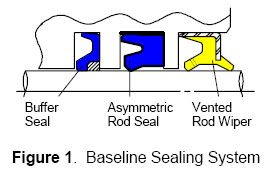
Baseline Sealing System
This system in Disogrin 9250 has decades of
proven field experience, but an upper
temperature limit of 100º C and is not
hydrolysis or bio-fluid resistant. This paper
centers
mostly on materials, and will show the results
of several new urethane and elastomeric blends
in designs equivalent to our baseline sealing
system.It should also be noted that many of the results
concentrate on the residual interference that
remains after test. This is a measurement of the
remaining interference the seal
has with the bore and shaft, which takes into
account not only wear but also the physical
state of the material. This is a strong
indicator of remaining life as a design is as
dependant upon the material resiliency to ensure
that it seals at low (or no) pressure as it is
the material strength to ensure that it does not
extrude at high loads.
MAIN SECTION
For several years we have supplied a proprietary
blend of urethane into the market (NOK U641)
that is capable of handling 110º C. As part of
the material development, the
baseline configuration was successfully lab
tested to 500km (0.5million cycles) at 32MPa /
0.4mm/s / 110º C without leakage. Our experience
indicates that the results of
this accelerated test correlate well with actual
field results. In this case the NOK U641 change
allows our sealing system to provide similar
hours to what was provided by
Disogrin 9250, but at an elevated temperature
(see figure 2). NOK U641 was also developed to
be hydrolosis and glycolosis resistant.
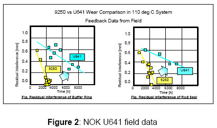
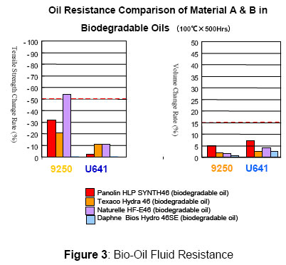
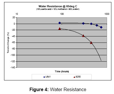
NOK UH05 – 120º C Urethane.
In many cases NOK U641 is all that is needed to
meet the application needs. It does not meet our
initial high and low temperature requirements
though, thereforeNOK UH05 was developed. NOK UH05 improves our
cold temperature resistance, while increasing
the high temperature capability (see figure 5).
The trade off with NOK
UH05 is that it is more difficult to process,
and therefore only suitable for the thinner
cross section of the buffer seal.
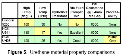
ELASTOMERS: G928=120ºC HNBR; A505=110ºC
NBR
As a complement to urethanes, we develop
specially formulated elastomers for use in
pressure applications. The advantage elastomers
can offer is that they takeless of a compression set than urethanes (see
figure 6), but they require back up support to
prevent extrusion at pressures above 12MPa (see
figure 7). Lowercompression set equates to improvements in
residual interference which is advantageous
where longer life is required. Extrusion is not
an issue as we have
successfully used filled / reinforced PTFE back
up rings to reach 40+MPa.
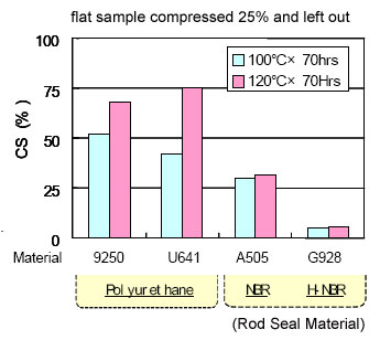
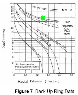
ELASTOMERIC ROD SEALING SYSTEM
We have successfully used combinations of
urethane and elastomer in Asia for numerous
years. A U641 buffer with A505 NBR rod seal
system (fig. 8) meets allof the design goals except for the 120º C upper
limit (max is 110º C). To meet the 120º C
requirement, we substitute UH05 for the buffer
seal, and HNBR G928 forthe rod seal.
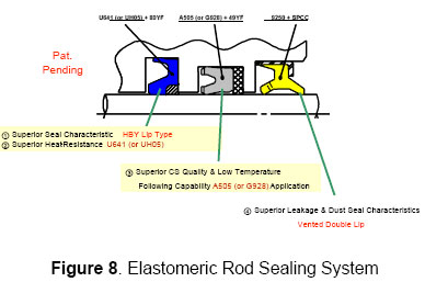
BIODEGRADABLE OIL COMPATIBILITY
Immersion testing was conducted for 500 hours at
100º C and 110º C in numerous biodegradable oils
to determine their effect on all previously
mentionedmaterials. Panolin HLP Synth46 was chosen as our
baseline biodegradable oil, and lab testing was
conducted on the systems shown in figure 8 at
80º C,100º C, 110º C, and 120º C for 125km @ 42MPa.
The results are shown in figure 9. All materials
performed well, with U641 starting to take a set
at its upper limit of110 deg C (as expected).
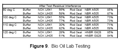
SYSTEM FOR N.A. AND DIN STANDARDS
The JIS standard groove sizes allow for a back
up ring independent of the rod seal material,
where as the North American and DIN standard
groove sizes do not. Thiscreates a problem with retrofit of the new
solutions into existing grooves. We have
developed a design that integrates the back up
into the seal (referred to as anIUY design – see figure 10) as a solution to
this.
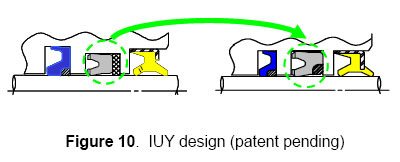
The IUY system was tested at 110º C and 120º C
for 500km @ 32MPa (0.4mm/s) against a NOK U641
rod seal (both using a NOK U641 buffer), and the
residualinterference results are shown in figure 11.
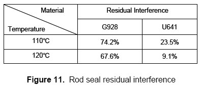
Although neither of the systems actually leaked,
the HNBR G928 has significantly higher residual
interference overall (especially at 120º) This
can bedirectly correlated to longer system life.
CONCLUSION
NOK U641 is a hydrolisis / glycolosis resistant
option for 110ºC systems with standard and bio
hydraulic oils provided 100% sealing at extreme
cold temperature isnot needed. If 100% sealing at extreme cold
temperature is needed, A505 NBR can be used in
combination with a back up ring for the rod
seal.
NOK UH05 (buffer) in combination with G928 HNBR
(rod seal) is a hydrolisis / glycolosis
resistant material option for 120ºC systems with
standard and biohydraulic oils. The HNBR rod seal does require a
back up ring to prevent extrusion though. Base
on our testing, this is the best sealing
solution for long life atany temperatures.
Field test show that the A505 (NBR) system can
go 8,000 hours in and excavator application, and
based on the improvement in seal residual
interference we expectthe G928 (HNBR) system could last 5X longer even
at elevated temperatures. The life of any system
is influenced by factors such as contamination,
rod damage, and oil
degradation which greatly effect seal life in
actual applications. Every system should be
tested in the actual application.
Standard Design Validation Test Fixture Example
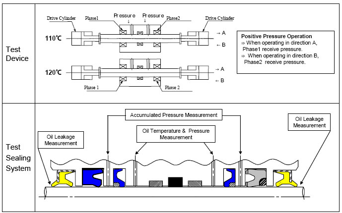
Simrit
Simrit Division of Freudenberg-NOK,
2250 Point Blvd.,
Suite 230, Elgin, IL 60123
847.428.1261
|
-
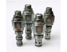 Floating
Cage Pressure Controls Floating
Cage Pressure Controls
Pressure control is a major factor in the
design and operation of safe, efficient and
reliable hydraulic systems. Limiting the
operating pressure to prevent damage to
hydraulic components and other expensive
equipment due to the resultant forces is one
of the most important functions of pressure
control valves. Pressure control valves may
also be used to control sequence of
operations, maintain critical holding
forces, and prevent loads from "running
away" due to the effects of gravity.
Types of Pressure Controls
Pressure controls are typically 2-way or
3-way valves, which are either normally
closed (non-passing flow) or normally open
(passing flow). The majority of them are
infinite positioning, which means they can
assume an infinite number of positions
between their fully open and fully closed
positions, depending on flow rates and
pressure differentials. Some pressure
controls are also available as pressure
breaker valves, commonly referred to as
kick-down valves. These valves are only two
position, and are either fully open or fully
closed. They open or close at a
pre-determined pressure, set by the spring,
then reverse their position when pressure to
the valve is reduced to near zero.
There are four common types of pressure
controls, three of which are discussed in
this article: reliefvalves,
pressure-reducing valves, sequence valves
and counterbalance valves.
Relief Valves
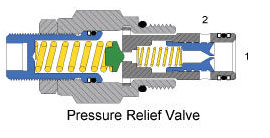 The
relief valve is the safeguard that limits
maximum pressure in a system by diverting
flow back to the tank when the valve’s
setting is reached. Relief valves are
normally closed, while, in contrast,
pressure-reducing valves are normally open.
Various types of relief valves include:
direct acting, differential area, piloted
and bi-directional. The
relief valve is the safeguard that limits
maximum pressure in a system by diverting
flow back to the tank when the valve’s
setting is reached. Relief valves are
normally closed, while, in contrast,
pressure-reducing valves are normally open.
Various types of relief valves include:
direct acting, differential area, piloted
and bi-directional.
Pressure Reducing Valves
-
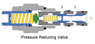 Pressure
reducing valves are used to reduce pressure
in certain parts of a hydraulic circuit that
may not be able to withstand the maximum
system pressure established by the relief
valve. With a pressure-reducing valve in the
system, pressure can be reduced to an
actuator downstream of the valve, without
affecting the pressure in the rest of the
system. Pressure-reducing valves are
normally open, and are available in 2-way
(non-relieving) and 3-way (relieving) types. Pressure
reducing valves are used to reduce pressure
in certain parts of a hydraulic circuit that
may not be able to withstand the maximum
system pressure established by the relief
valve. With a pressure-reducing valve in the
system, pressure can be reduced to an
actuator downstream of the valve, without
affecting the pressure in the rest of the
system. Pressure-reducing valves are
normally open, and are available in 2-way
(non-relieving) and 3-way (relieving) types.
Sequence Valves
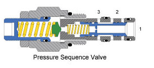 As
its name implies, a sequence valve causes
operations in a hydraulic circuit to take
place in a given sequence, without the use
of electrical switches and controls.
Sequence valves can be normally open or
normally closed, depending on the
application in which they are used, but are
typically 2-way normally closed valves, and
are either internally or externally piloted.
Some sequence valves are 3-way, and can be
normally open or normally closed. As
its name implies, a sequence valve causes
operations in a hydraulic circuit to take
place in a given sequence, without the use
of electrical switches and controls.
Sequence valves can be normally open or
normally closed, depending on the
application in which they are used, but are
typically 2-way normally closed valves, and
are either internally or externally piloted.
Some sequence valves are 3-way, and can be
normally open or normally closed.
Counterbalance Valves
Counterbalance valves are used when there is
a need to control a load. They maintain a
set pressure opposite of the load, to keep
it from free falling. They may also serve as
a full-flow relief valve. Pleaseread our
article on Counterbalance Valves for more
information.
The Problems
Due to the nature of most cartridge-type
pressure control valve designs, they
typically require a very precise forming of
the valve cavity to ensure reliable
operation. If the valve cavity is not
machined within required tolerances, the
valve tends to bind against the walls of the
valve cavity. This can cause distortion of
the cage and subsequent valve failure due to
binding or sticking of the spool or poppet.
Often, the cartridge valve is removed,
assumed to be defective, and a different
valve is installed in the cavity with the
same results.
After a number attempts with different
valves it may be determined that the cavity
must be reworked to solve the problem. It
should be noted, however, that reworking a
cavity might also create another problem in
that the cavity may become oversized, and
will not provide enough squeeze on the
o-rings to ensure a proper seal.
Another problem with cartridge type pressure
controls is that they are often used in an
environment that is prone to significant
changes in temperature. This causes thermal
expansion and contraction of the manifold
and valve parts. Valves with a minimal
margin of concentric clearance between the
cage and the cavity may function properly
with cold oil, but when exposed to hot oil,
will experience binding and sticking
failures because of the thermal expansion of
parts in the hot fluid.
And last, but certainly not uncommon, over-torqueing
the cartridge into the cavity during
installation is another problem that will
cause a valve spool or poppet to stick.
Naturally, it is desirable to torque the
cartridge into the manifold as much as
possible to prevent it from backing out.
The Solution
The
patented floating cage concept, designed by
Command Controls Corp. of Elgin, Illinois
solves the age-old problem of valve spool
binding in pressure control valves caused by
cage distortion. The floating cage, used in
many of Command Controls’ flow controls,
allow the cartridge to be flexible enough to
conform to the contour of the valve cavity
independently of the cartridge valve
threads. This allows the cartridge to fit
into the cavity without putting any side
load on the valve, even in
cases where the cavity may be non-concentric
or out-of-round, thereby allowing the spool
to move freely without binding. Distortion
of the cage, due to the effects of thermal
expansion, is also eliminated by the
floating cage design.
In the floating cage concept, since the
retainer and cage are not physically
connected to each other, torque applied to
the threads when installing the cartridge in
the manifold is not transferred to the cage.
This yields another side-benefit: Command
Controls floating-cage cartridges can be
torqued into manifolds with higher torques
than most other cartridge valves, and as
such, are less likely to vibrate loose and
cause external oil leakage. The floating
cage design, along with other unique designs
and innovations, put Command Controls’
cartridge valves on the leading edge of
cartridge valve technology.
- - -
Written by Connie Kosarzecki of Command
Controls Corp., Elgin, Ill. Kosarzecki has
worked in the fluid power industry since
1958. Command Controls Corp, established in
1993, manufactures a complete line of
state-of-the-art, highpressure (5,000
psi/350 bar), high-performance, screw-in,
cartridge-type, hydraulic control valves and
manifold systems for the fluid power
industry. For more information, please visit
www.commandcontrols.com.
|
-
 Rexroth
Hydrostatic Regenerative Braking System
(HRB) Makes Commercial Vehicles Up to 25
Percent More Economical Rexroth
Hydrostatic Regenerative Braking System
(HRB) Makes Commercial Vehicles Up to 25
Percent More Economical
Rexroth hydrostatic regenerative braking
system (HRB) reduces fuel consumption by up
to 25 percent and can be retrofitted as an
add-on system even in vehicles without
hydraulics.
Hydrostatic regenerative braking system
(HRB) stores brake energy in a hydraulic
pressure reservoir and relieves the load on
the main drive when the vehicle is
accelerating – potentially reducing fuel
consumption by up to 25 percent.
(Bethlehem, PA - www.boschrexroth-us.com)
Bosch Rexroth’s hydrostatic regenerative
braking (HRB) system includes a hydrostatic
hybrid drive which uses the considerably
higher performance of hydraulics compared
with available batteries to substantially
reduce fuel consumption even in heavy
commercial vehicles.
When the driver presses the brake pedal, a
hydraulic unit integrated in the drivetrain
presses the hydraulic fluid into a
high-pressure reservoir. The resulting
resistance makes the vehicle decelerate.
When accelerating, the hydraulic pressure
reservoir is controlled electronically to
release the pressure and it relieves the
load on the diesel engine. As a result, the
engine consumes less fuel, generates less
exhaust gases, and functions more quietly.
The compact Rexroth HRB is ideal for use in
various commercial vehicles. The HRB can be
integrated and even retrofitted in the
chassis as an add-on system, without major
modifications.
The system reduces fuel consumption by up to
25 percent in vehicles used for very short
distances such as urban buses, garbage
trucks, fork lift trucks, or delivery
vehicles driven in city traffic. Fuel
consumption can also be reduced considerably
in other commercial vehicles and trucks used
for intercity service.
Each time a driver brakes, the HRB system
stores energy which would otherwise be lost.
The hydrostatic hybrid drive functions
almost maintenance-free and wear-free
compared with electric hybrid drives. For
example, it is not necessary to regularly
change the battery. In addition, the HRB
also improves the acceleration of the
vehicle. The additional drive energy allows
vehicles to be equipped with smaller diesel
engines and therefore further reduce fuel
consumption and emissions.
All Rexroth HRB components are based on
standard components from the manufacturer's
current product portfolio. Prototypes of the
Rexroth hydrostatic hybrid drive are
currently being tested in on-road vehicles.
|
 CONEXPO-CON/AGG
2008 and IFPE 2008 CONEXPO-CON/AGG
2008 and IFPE 2008
set records for attendance and exhibit space
Construction, construction materials and power
transmission industry leaders unveil latest
product technologies and innovations
CONEXPO-CON/AGG 2008 and the co-located IFPE
2008 expositions have set records for
attendance, exhibit space and number of
exhibiting companies. In addition,
CONEXPO-CON/AGG 2008 is the largest trade show
in North America of any industry in 2008.
CONEXPO-CON/AGG and IFPE are known as global
showcases of the latest equipment, product
innovations and technological advances for the
construction, construction materials and power
transmission industries.
More than 144,600 industry professionals from
around the world attended CONEXPO-CON/AGG 2008
and IFPE 2008 during their five-day run March
11-15, 2008 at the Las Vegas Convention Center
in Las Vegas, USA.
CONEXPO-CON/AGG 2008 covered more than 2.28
million net square feet of exhibits (211,966 net
square meters), taken by 2,182 exhibitors, and
was 21 percent bigger than the last show, held
in 2005.
IFPE 2008 was also the largest in its history
with more than 129,000 net square feet of
exhibit space (11,994 net square meters) used by
469 exhibitors – a 16 percent increase in space
compared to 2005.
International Attendance
A record number of international industry
professionals visited the shows – more than
28,000, which is more than 19 percent of total
attendance and represents more than 30 percent
growth compared to the last edition of the
shows. International attendance increased by
more than 50 percent from the Latin America and
Caribbean marketplace, and doubled from China,
India and Turkey. There were also significant
increases from Canada, Australia, Russia and the
Middle East, to name just a few.
International visitors to the shows hailed from
more than 130 non-U.S. countries. There were
more than 60 official international customer
delegations organized by the U.S. Department of
Commerce as well as in-country trade
associations and related groups.
Exhibit Features
The show floor included a record number (14) of
international exhibit pavilions highlighting
products and services developed outside the
United States - CONEXPO-CON/AGG 2008 with 10,
from Brazil, Canada, China, Finland, Germany,
Italy, Korea, Spain, Turkey and the United
Kingdom, and IFPE 2008 with four, from China,
Italy, Spain and Taiwan. -more-
IFPE 2008 hosted a new exhibit pavilion
sponsored by the American Gear Manufacturers
Association (AGMA), welcomed back a Power
Transmission Distributors Association (PTDA)
pavilion, and set up a new pavilion to highlight
the expanded presence of sensors at the show.
CONEXPO-CON/AGG 2008 featured a new Safety Zone
of exhibits and demonstrations from industry and
government groups, including the U.S.
Occupational Safety and Health Administration,
Mine Safety and Health Administration, National
Institute of Occupational Safety and Health, and
the Aerial Work Platform Training/International
Powered Access Federation.
Education Highlights
The CONEXPO-CON/AGG 2008 seminar program offered
a record 130 sessions. Show education expanded
in 2008 to include a special seminar on best
practices for small fleet management. Also new:
select education sessions were offered via
LiveCasts and podcasts to extend the value of
show education. Education session registrations
totaled more than 22,850.
IFPE 2008 also expanded its educational
offerings with an electronic controls symposium
added to the show’s renowned Technical
Conference. The conference offered a record 111
papers from industry experts from around the
world. A new IFPE Innovation and Solutions
Center, on the show floor, provided real world
insights into future design applications. IFPE
education session registrations totaled more
than 1,700.
Industry Support
The shows were the industry gathering place in
2008. Some 105 allied industry groups were
“supporting organizations" of CONEXPO-CON/AGG
2008 and IFPE 2008, bringing their memberships
to the shows. In addition to U.S-based groups,
these included international industry-related
organizations from Brazil, Canada, Chile, China,
Finland, Germany, India, Japan, Korea, Mexico,
Spain, Taiwan, Turkey, United Kingdom and
Venezuela.
A record number of 11 associations held annual
conventions or board meetings at the shows, and
overall a record number of more than 530
industry-related meetings were held in
conjunction with CONEXPO-CON/AGG 2008 and IFPE
2008.
Other Highlights
CONEXPO-CON/AGG 2008 hosted a visit by Admiral
Woody Sutton, the U.S. Department of Commerce
Assistant Secretary for Manufacturing and
Services, on March 12. Sutton toured the show
and met with show officials and exhibitors to
discuss global trade issues.
CONEXPO-CON/AGG 2008 was also the site of the
first ever Construction Challenge competition,
initiated by show organizer Association of
Equipment Manufacturers (AEM). The creative
problem-solving competition was designed to
interest teens in construction careers, while
calling attention to industry workforce
shortages and infrastructure renewal needs.
The next edition of the triennial shows will be
March 22-26, 2011 at the Las Vegas Convention
Center in Las Vegas, USA. Check online for
details: www.conexpoconagg.com,
www.ifpe.com.
|
|
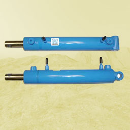 SENSING
HYDRAULIC CYLINDER SENSING
HYDRAULIC CYLINDER
Polygon Company, Walkerton Indiana, March 2008
Ever since the inception of composite materials
an engineering conundrum has developed regarding
the process of how to integrate composites and
metals into a working relationship, which
benefits upon each constituents performance
properties. For composite applications to gain
any real traction within traditional metallic
OEM markets, a significant bridge needs to be
crossed with respect to making them
manufacturing friendly within existing metallic
manufacturing infrastructures.
Polygon has taken a significant step in that
direction through the creation of a composite
sleeve inserted within ametallic tube for
hydraulic cylinder applications. In addition to
this manufacturing friendly concept the added
feature of electronic sensing and positioning is
included. This new sensing hydraulic cylinder
contains a composite/metallic barrel, which can
have ends that are attached using existing
welding or threading techniques. This patented
process allows the composite inner tube to carry
almost the entire hydraulic pressure force while
the outer metallic tube keeps the structure
round. This engineering feat was possible by
incorporating the anisotropic expansion
characteristics of composites while
simultaneously being constrained within the
isotropic properties of a metallic shell. The
circumferential pressure properties within a
composite tube can be altered or manipulated
through fiber path geometry.This feature allows
the composite tube to slightly expand under
pressure, which is in turn immediately contained
by the metallic outer structure. It also
eliminates the metallic tubing producers concern
that the tolerance interface conditions between
inserting two tubes together without any
machining as a practical impossibility.
A serendipitous side benefit is that now
hydraulic cylinder manufacturers can use thin
walled, low-grade tubing to
make this technology work. The metallic outer
tubing does not have to be honed or plated.
Because the composite inner tube does most of
the pressure work; low cost aluminum tubing can
now even become an option as well. The
non-magnetic properties of aluminum also afford
new possibilities for additional externally
mounted andpre-existing positioning devices to
be used. This tube insertion technology is
creating new opportunities to attack a very
mature market with many new possibilities.
To take this technology to a whole new level is
the additional potential of relaying the sensing
signal, via existing asset management or control
systems, to a centralized location via wireless
access or
even satellite tracking. In real time Polygon
can supply this new sensing cylinder technology
for
construction OEM manufactures that might have
the need for such interpretative data or
situational
awareness such as a cylinder requiring
maintenance for safety purposes.
|
|
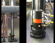 The
Case for Safety Catchers The
Case for Safety Catchers
Ken Davis, Business Development Manager,
Advanced Machine & Engineering Co.
The Europeans have the answer to safeguarding
hydraulic and pneumatic presses from
catastrophic failure. The good news: now it’s
available here in the U.S.
An ounce of prevention is worth a pound of
cure…the old adage rings especially true for the
thousands of press operators today trying to
reduce their production costs and stay
competitive with higher speeds, smaller batches
and – keep your fingers crossed – greater
machine uptime. The cost today for a
catastrophic press failure? On the low end,
certainly thousands of dollars in lost
production time and die replacement costs. On
the high end, the loss of a key operator due to
injury or a customer that takes his business
elsewhere rather than run the risk of falling
behind schedule again.
Sure, today’s most modern hydraulic and
pneumatic presses have a variety of OSHA
mandated protection systems in place to ensure
operator safety. Guards, interlocks,
electro-sensitive and opto-electronic devices,
emergency stop devices and other redundant
systems have helped make presses safer in recent
years. But when it comes to safeguarding the
presses themselves from expensive damage to the
press or dies, standards in the U.S. fall well
short of their European CEN counterpart, which
states in prEN 693 Machine tools Safety
Hydraulic Presses: “Where there is a risk…from a
gravity fall of the slide /ram a mechanical
restraint device, e.g. a scotch, shall be
provided to be inserted in the press…On presses
with an opening stroke length of more than 500
mm and a depth of table of more than 800 mm, the
device shall be permanently fixed and integrated
with the press.” A similar CSA Standard
(Z142-02) exists in Canada…
‘Faulty’ vs. ‘failsafe’. For most American press
operators, however, a ratchet bar, locking bolt
or latch is all that’s standing between them and
a catastrophic crash should hydraulic or
pneumatic pressure be lost suddenly or the
lifting mechanism experience a mechanical
breakage. When functioning properly, the ratchet
system -- usually running the length of the
press stroke-- does an adequate job of arresting
the fall of the ram and preventing a
catastrophic crash. A spring latch will
automatically extend to engage the teeth of the
ratchet at some point before a crash can occur.
Unfortunately, the ratchet is a wear part that
after hundreds, even thousands of press cycles
can begin to exhibit signs of wear that are
difficult to detect visually, and probably can’t
be heard, by even the most experienced operator.
Over time, the ratchet teeth, spring and latch
typically begin to wear, since the spring latch
makes contact with the teeth (but doesn’t
engage) on the upstroke of the ram every time
the ram is raised for the next part. The
ratchet, and even the end of the spring latch,
can wear to the point where a fall can’t be
prevented.
In addition, locking bolts and latches often
operate only at the top of the stroke, and
ratchet bars at fixed interval positions.
Consequently, the ram must often be retracted to
its full stroke position each and every part,
despite the fact that the part requires only a
short opening stroke. This can add considerable,
and very expensive, non-productive time to the
cycle.
But in Europe, Canada and elsewhere in the
world, most presses are equipped with a SITEMA
Safety Catcher, which satisfies the requirements
of CEN and CSA safety standards, foolproofs
presses from a catastrophic crash, and allows
the operator to optimize the stroke for any size
part. The SITEMA Safety Catcher works a little
like the ‘Chinese Finger Trap’ you probably
played with as a child. You could easily put
your finger in one end of the paper cylinder,
but it was very difficult to retract it. In
fact, the harder you pulled the more clamping
power the simple paper cylinder seemed to exert
on your finger. The SITEMA Safety Catcher works
in similar fashion. If hydraulic or pneumatic
system pressure fails, or if a rope, chain, belt
or toothed drive breaks, the SITEMA Safety
Catcher prevents the load from crashing down at
any position of the descent. Better yet, the
system is ‘self-intensifying’, so that as
downward force increases, so too does the Safety
Catcher’s clamping force.
Here’s how it works (see Fig. 2 and 3):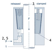
1) A cylinder rod is mounted to the top of the
platen extending through the press crown and the
Sitema safety catcher housing (Figure 2). The
safety catcher housing is securely fixed to the
machine crown / frame and surrounds the rod
which is free to move during normal operation.
Wedge shaped clamping jaws inside the housing
are held with hydraulic or pneumatic pressure to
keep the wedges in position so that the rod can
move freely.
2) This Safety Catcher instantly becomes
effective when hydraulic or pneumatic pressure
is lost or released. A spring causes the
clamping jaws to firmly contact the rod. As a
result, any downward movement of the rod
initiates the “self-intensification” feature
securing the load.
3) Significantly, the energy of the falling or
sinking load is used to apply additional
clamping force if needed. In other words,
‘self-intensifying’ friction created between the
clamping jaws and the cylinder rod draws the
jaws into their maximum clamping position after
only a few millimeters of movement.
4) If the load continues to increase, the Safety
Catcher will continue to hold the rod in a fixed
position until a pre-determined static holding
force limit is exceeded – (approximately 3-4
times the retain force). Beyond that point, the
Safety Catcher continues to safely hold the rod,
with a braking action dissipating the kinetic
energy of the falling mass while it continues to
resist the downward movement of the platen.
5) Only when hydraulic or pneumatic pressure is
restored in conjuction with the equivalent
reverse movement of the rod are the clamping
wedges released, making the SITEMA Safety
Catcher inherently failsafe.
SITEMA is ‘catching on’ everywhere. From presses
to large hydraulic elevators to stack loaders to
machine tools – in almost any application where
a large load is traveling and the potential for
a catastrophic mechanical failure exists –
SITEMA Safety Catchers have been applied
successfully and in increasing numbers, as
safety standards toughen around the world. They
are available in a variety of sizes to meet most
common press sizes, including the very largest.
Most importantly, they are readily available
today in the United States through Advanced
Machine and Engineering Co.
About AME
AME is a global manufacturer and distributor of
precision machine components, fluid power
components, fixturing/workholding, power drawbar
and spindle interface components, and saw
machines and blades. The company also designs
and builds special machines for a variety of
industries, and provides machine rebuilding,
retrofitting and contract manufacturing
services. AME has partners and customers around
the world and across the U.S. To learn more,
visit www.ame.com.
|
-
 Bob
and Dan's "boring" adventure Bob
and Dan's "boring" adventure
Cutting two eight-mile subway tunnels
through varying Santa Monica Mountain rock
formations is a dirty business. But someone
had to do it.
-
- Construction & Tunneling
Services, Inc. (CTS), Kent, WA, an
established design engineer and supplier of
mechanical excavation equipment for the
construction and mining communities, has
kept two tunnel boring machines (TBMs) over
25 years old in service with the help of
Bosch Rexroth.
The two TBMs were used by specialty
underground contractor Traylor Bros., Inc.,
of Evansville, Indiana, on the Red Line
Metro project owned by the Los Angeles
County Metropolitan Transport Authority.
The Red Line Metro project required the
construction of two 12,500-meter subway
tunnels traversing the Santa Monica
Mountains near the famous Hollywood sign.
The final tunnel was a cast-in-place
concrete lining of 5.44-meter diameter, so
the job required two tunnel boring machines
with a bore diameter of 6.3 meters.
CTS had to engineer and remanufacture two
existing TBMs, resizing them with new
cutterheads and shields and adding a
hydraulic drive, taking advantage of Bosch
Rexroth's broad technical product line.
 "Hydraulic
components consisting of pumps, motors, and
valves were integrated with custom gearing
and specialty hydraulic cylinders to provide
the bulk of the critical pieces that the
tunnel machine requires to operate at its
peak," said Dan Nowak, CTS president. "Our
experience with this job reaffirmed what we
have known from previous work with Bosch
Rexroth - they make good products that fit
in major areas of machinery design, they
understand how these parts perform and where
they should be applied for best results. I
don't think you will find an operating
tunnel machine that doesn't have a Bosch
Rexroth part on it." "Hydraulic
components consisting of pumps, motors, and
valves were integrated with custom gearing
and specialty hydraulic cylinders to provide
the bulk of the critical pieces that the
tunnel machine requires to operate at its
peak," said Dan Nowak, CTS president. "Our
experience with this job reaffirmed what we
have known from previous work with Bosch
Rexroth - they make good products that fit
in major areas of machinery design, they
understand how these parts perform and where
they should be applied for best results. I
don't think you will find an operating
tunnel machine that doesn't have a Bosch
Rexroth part on it."
The job was not without surprises. The first
reach of these tunnels traversed soft rock,
then encountered a soil-like material,
almost plastic in places. Other materials
included squeezing shales, sandstones,
conglomerates, and granodiorites.
"The opinion of both the operating
contractor and the CTS staff at the end of
the job was that without the variable speed
features and the higher torque capacity
offered by the Rexroth hydraulics, the
project would not have had such a mechanical
success," according to Nowak.
If you've got a mountain of dirt to uncover
and an unyielding deadline to meet, talk to
the people with big ideas and the brawn to
back them up. Bosch Rexroth.

Bosch Rexroth Corporation
2315 City Line Road
Bethlehem, PA 18017-2131
Telephone (610) 694-8298
Fax (610) 694-8339
|
 When
Morrell Inc, Schuler Inc and Bosch Rexroth
teamed up, they proved that global manufacturing
of auto parts with local control in Michigan was
the right path for helping the Big Three achieve
more productivity. When
Morrell Inc, Schuler Inc and Bosch Rexroth
teamed up, they proved that global manufacturing
of auto parts with local control in Michigan was
the right path for helping the Big Three achieve
more productivity.
The world's first crossbar transfer press,
developed by Schuler AG, in the early 1990's,
revolutionized auto parts stamping plants
throughout the auto industry.
Today's compact crossbar transfer press is used
not only for large unstable auto body panels,
but also for production of mid-sized parts such
as doors and engine hoods.
Through the use of a compact transfer press and
the unique partnership of Morrell, Schuler and
Bosch Rexroth, both Ford Motor Company and
General Motors are able to produce new hoods and
doors while improving productivity, design
flexibility and a reduction in costs.
Critical to the success of this global-local
team effort was the teams ability to meet the
scrutiny of design engineers in Germany, while
also providing local installation and testing in
Auburn Hills, Michigan. Schuler was also able to
work with a single rep for all technologies
while supplying contact for everyone.
If you would like to forge an application
engineering partnership, across technologies,
continents, companies, Bosch Rexroth can help.
|
| |
| |
|